


73
SCHEDULED MAINTENANCE
Establish a regular maintenance schedule based on your ac-
tual chiller requirements such as chiller load, run hours, and
water quality. The time intervals listed in this section are
offered as guides to service only.
Service Ontime —
The CVC/ICVC will display a SER-
VICE ONTIME value on the MAINSTAT screen. This value
should be reset to zero by the service person or the operator
each time major service work is completed so that the time
between service can be viewed and tracked.
Inspect the Control Panel —
Maintenance consists of
general cleaning and tightening of connections. Vacuum the
cabinet to eliminate dust build-up. If the chiller control mal-
functions, refer to the Troubleshooting Guide section for con-
trol checks and adjustments.
Check Safety and Operating Controls Monthly —
To ensure chiller protection, the automated Control Test
should be performed at least once per month. See Table 3
for safety control settings. See Table 9 for Control Test
functions.
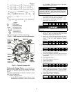
Changing Oil Filter —
Change the oil filter on a
yearly basis or when the chiller is opened for repairs. The
19XR has an isolatable oil filter so that the filter may be
changed with the refrigerant remaining in the chiller. Use
the following procedure:
1. Ensure the compressor is off and the disconnect for the
compressor is open.
2. Disconnect the power to the oil pump.
3. Close the oil filter isolation valves located behind power
panel on top of oil pump assembly.
4. Connect an oil charging hose from the oil charging valve
(Fig. 2) and place the other end in a clean container suit-
able for used oil. The oil drained from the filter housing
should be used as an oil sample and sent to a laboratory
for proper analysis. Do not contaminate this sample.
5. Slowly open the charging valve to drain the oil from the
housing.
6. Once all oil has been drained, place some rags or absor-
bent material under the oil filter housing to catch any
drips once the filter is opened. Remove the 4 bolts from
the end of the filter housing and remove the filter cover.
7. Remove the filter retainer by unscrewing the retainer nut.
The filter may now be removed and disposed of properly.
8. Replace the old filter with a new filter. Install the filter re-
tainer and tighten down the retainer nut. Install the filter
cover and tighten the 4 bolts.
9. Evacuate the filter housing by placing a vacuum pump on
the charging valve. Follow the normal evacuation proce-
dures. Shut the charging valve when done and reconnect
the valve so that new oil can be pumped into the filter
housing. Fill with the same amount that was removed;
then close the charging valve.
10. Remove the hose from the charging valve, open the isola-
tion valves to the filter housing, and turn on the power to
the pump and the motor.
Oil Specification —
If oil is added, it must meet the fol-
lowing Carrier specifications:
Oil Type for units using R-134a . . . . . . . . . . . . . . . . . . Inhibited
polyolester-based synthetic
compressor oil formatted for
use with HFC, gear-driven,
hermetic compressors.
ISO Viscosity Grade . . . . . . . . . . . . . . . . . . . . . . . . . . . . . . . . 68
The polyolester-based oil (P/N: PP23BZ103) may be
ordered from your local Carrier representative.
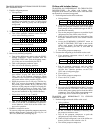
Oil Changes —
Carrier recommends changing the oil af-
ter the first year of operation and every five years thereafter as
a minimum in addition to a yearly oil analysis. However, if a
continuous oil monitoring system is functioning and a yearly
oil analysis is performed, the time between oil changes can be
extended.
TO CHANGE THE OIL
1. Transfer the refrigerant into the chiller condenser vessel
(for isolatable vessels) or to a pumpout storage tank.
2. Mark the existing oil level.
3. Open the control and oil heater circuit breaker.
4. When the chiller pressure is 5 psig (34 kPa) or less, drain
the oil reservoir by opening the oil charging valve
(Fig. 2). Slowly open the valve against refrigerant
pressure.
5. Change the oil filter at this time. See Changing Oil Filter
section.
6. Change the refrigerant filter at this time, see the next sec-
tion, Refrigerant Filter.
7. Charge the chiller with oil. Charge until the oil level is
equal to the oil level marked in Step 2. Turn on the power
to the oil heater and let the PIC II warm it up to at least
140 F (60 C). Operate the oil pump manually, using the
Control Test function, for 2 minutes. For shutdown condi-
tions, the oil level should be full in the lower sight glass.
If the oil level is above
1
/
2
full in the upper sight glass, re-
move the excess oil. The oil level should now be equal to
the amount shown in Step 2.
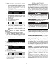
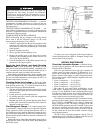
Refrigerant Filter —
A refrigerant filter/drier, located on
the refrigerant cooling line to the motor, should be changed
once a year or more often if filter condition indicates a need for
more frequent replacement. Change the filter by closing the fil-
ter isolation valves (Fig. 4) and slowly opening the flare fittings
with a wrench and back-up wrench to relieve the pressure. A
moisture indicator sight glass is located beyond this filter to in-
dicate the volume and moisture in the refrigerant. If the mois-
ture indicator indicates moisture, locate the source of water im-
mediately by performing a thorough leak check.
Oil Reclaim Filter —
The oil reclaim system has a
strainer on the eductor suction line, a strainer on the discharge
pressure line, and a filter on the cooler scavenging line.
Replace the filter once per year or more often if filter condition
indicates a need for more frequent replacement. Change the fil-
ter by closing the filter isolation valves and slowly opening the
flare fitting with a wrench and back-up wrench to relieve the
pressure. Change the strainers once every 5 years or whenever
refrigerant is evacuated from the cooler.
Ensure power to the control center is off when cleaning and
tightening connections inside the control panel.
The oil filter housing is at a high pressure. Relieve this
pressure slowly.