


83
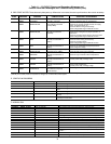
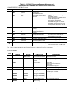
Table 11 — CVC/ICVC Primary and Secondary Messages and
Custom Alarm/Alert Messages with Troubleshooting Guides (cont)
I. CHILLER PROTECT LIMIT FAULTS (cont)
*[LIMIT] is shown on the CVC/ICVC as the temperature, pressure, voltage, etc., set point predefined or selected by the operator as an override,
alert, or alarm condition. [VALUE] is the actual pressure, temperature, voltage, etc., at which the control tripped.
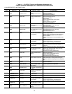
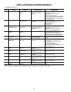
J. CHILLER ALERTS
STATE
PRIMARY
MESSAGE
SECONDARY
MESSAGE
ALARM MESSAGE
PRIMARY CAUSE
ADDITIONAL
CAUSE/REMEDY
246
PROTECTIVE
LIMIT
INVALID DIFFUSER
CONFIG
246->Diffuser Control Invalid
Configuration:
Check SETUP2 Entries.
Check diffuser/guide vane schedule.
247
PROTECTIVE
LIMIT
DIFFUSER POSITION
FAULT
247->Diffuser Position Fault:
Check Guide Vane and Diffuser
Actuators
Check rotating stall transducer wiring and
accuracy.
Check diffuser schedule.
Check for proper operation of diffuser actuator
and inlet guide vane actuator.
Check diffuser coupling.
Check inlet guide vane operation.
Check inlet guide vane calibration.
Check diffuser/inlet guide vane schedule.
Check diffuser mechanical set-up for proper
orientation.
If not using variable diffuser, check that the
option has not been enabled.
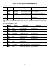
248
PROTECTIVE
LIMIT
SPARE TEMPERATURE
#1
248->Spare Temperature #1
[VALUE] exceeded limit of
[LIMIT]*.
249
PROTECTIVE
LIMIT
SPARE TEMPERATURE
#2
249->Spare Temperature #2
[VALUE] exceeded limit of
[LIMIT]*.
250
PROTECTIVE
LIMIT
REFRIGERANT LEAK
SENSOR
250->Refrigerant Leak Sensor
[VALUE] exceeded Limit of
[LIMIT]*.
The refrigerant leak detector’s output wired to
J5-5 and J5-6 on the CCM module has
reached the alarm limit.
Check leak detector and for leaks.
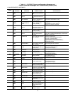
251
PROTECTIVE
LIMIT
ISM CONFIG
CONFLICT
251->ISM Config Conflict (ISM
Uploaded); Verify to Reset Alarm
Confirm valid settings in ISM_CONF screen.
252
PROTECTIVE
LIMIT
ISM CONFIG
CONFLICT
252->ISM Config Conflict (ISM
Downloaded); Verify to Reset
Alarm
Confirm valid settings in ISM_CONF screen.
253
PROTECTIVE
LIMIT
GUIDE VANE
CALIBRATION
253->Guide Vane Fault [VALUE].
Check Calibration.
Enter Control Test and execute Guide Vane
Calibration. Check guide vane feedback (ter-
minals J4-9 and J4-10) on the CCM module.
STATE
PRIMARY
MESSAGE
SECONDARY
MESSAGE
ALARM MESSAGE
PRIMARY CAUSE
ADDITIONAL
CAUSE/REMEDY
140
SENSOR ALERT LEAVING COND
WATER TEMP
140->Sensor Fault:
Check Leaving Cond Water
Sensor
Check sensor resistance or voltage drop.
Check for proper wiring.
141
SENSOR ALERT ENTERING COND
WATER TEMP
141->Sensor Fault:
Check Entering Cond Water
Sensor
Check sensor resistance or voltage drop.
Check for proper wiring.
142
LOW OIL PRESSURE
ALERT
CHECK OIL FILTER 142->Low Oil Pressure Alert.
Check Oil Filter.
Check for partially or closed shut-off valves.
Check oil filter.
Check oil pump and power supply.
Check oil level.
Check for foaming oil at start-up.
Check transducer wiring and accuracy.
143
AUTORESTART
PENDING
LINE PHASE
LOSS
143->Line Phase Loss Power loss has been detected in any phase.
Chiller automatically restarting.
144
AUTORESTART
PENDING
LINE VOLTAGE
DROP OUT
144->Single Cycle Line
Voltage Dropout
A drop in line voltage has been detected within
2 voltage cycles. Chiller automatically restarting if
Autorestart option is enabled.
145
AUTORESTART
PENDING
HIGH LINE
VOLTAGE
145>Line Overvoltage —
Average Line Volt [VALUE]
Check line power.
146
AUTORESTART
PENDING
LOW LINE
VOLTAGE
146->Line Undervoltage —
Average Line Volt [VALUE]
Check line power.
147
AUTORESTART
PENDING
STARTER MODULE
RESET
147->Starter Module Power-
On Reset When Running
ISM has detected a hardware fault and has reset.
Chiller automatically restarting.
148
AUTORESTART
PENDING
POWER LOSS 148->Control Power-Loss
When Running
Check control power.