


38
Condenser Freeze Prevention —
This control algo-
rithm helps prevent condenser tube freeze-up by energizing the
condenser pump relay. The PIC II controls the pump and, by
starting it, helps to prevent the water in the condenser from
freezing. The PIC II can perform this function whenever the
chiller is not running except when it is either actively in pump-
down or in pumpdown/lockout with the freeze prevention
disabled.
When the CONDENSER REFRIG TEMP is less than or
equal to the CONDENSER FREEZE POINT, the CONDENS-
ER WATER PUMP is energized until the CONDENSER RE-
FRIG TEMP is greater than the CONDENSER FREEZE
POINT plus 5° F (2.7° C) and the ENTERING CONDENSER
WATER TEMPERATURE is less than or equal to the CON-
DENSER FREEZE POINT. An alarm is generated if the chiller
is in PUMPDOWN mode and the pump is energized. An alert
is generated if the chiller is not in PUMPDOWN mode and the
pump is energized. If the chiller is in RECYCLE SHUT-
DOWN mode, the mode will transition to a non-recycle
shutdown.
Evaporator Freeze Protection (ICVC only) —
A
refrigerant temperature sensor is installed at the bottom of the
cooler to provide redundant freeze protection. In place of the
cooler and condenser water pressure transducer inputs on the
CCM is a 4.3k ohm resister and a jumper lead. When the
EVAPORATOR REFRIGERANT TEMPERATURE is less
than the EVAP REFRIG TRIPPOINT plus the REFRIG
OVERRIDE DELTA T (configurable from 2
°
to 5
°
), state 122
will be displayed and a capacity override will occur. If the
EVAPORATOR REFRIG TEMP is equal to or less than the
EVAP Refrig TRIPPOINT, Protective Limit ALARM STATE
232 will be displayed and the unit will shut down.
Tower Fan Relay Low and High —
Low condenser
water temperature can cause the chiller to shut down when re-
frigerant temperature is low. The tower fan relays, located in
the starter, are controlled by the PIC II to energize and deener-
gize as the pressure differential between cooler and condenser
vessels changes. This prevents low condenser water tempera-
ture and maximizes chiller efficiency. The tower fan relay can
only accomplish this if the relay has been added to the cooling
tower temperature controller.
The tower fan relay low is turned on whenever the condens-
er water pump is running, flow is verified, and the difference
between cooler and condenser pressure is more than 30 psid
(207 kPad) for entering condenser water temperature greater
than 65 F (18.3 C).
The tower fan relay low is turned off when the condenser
pump is off, flow is stopped, or the cooler refrigerant tempera-
ture is less than the override temperature for ENTERING CON-
DENSER WATER temperature less than 62 F (16.7 C), or the
differential pressure is less than 25 psid (172.4 kPad) for enter-
ing condenser water less than 80 F (27 C).
The tower fan relay high is turned on whenever the
condenser water pump is running, flow is verified and the dif-
ference between cooler and condenser pressure is more than
35 psid (241.3 kPa) for entering condenser water temperature
greater than the TOWER FAN HIGH SETPOINT (SETPOINT
menu, default 75 F [23.9 C]).
The tower fan relay high is turned off when the condenser
pump is off, flow is stopped, or the cooler refrigerant tempera-
ture is less than the override temperature and ENTERING
CONDENSER WATER is less than 70 F (21.1 C), or the differ-
ence between cooler and condenser pressure is less than
28 Psid (193 kPa), or ENTERING CONDENSER WATER
temperature is less than TOWER FAN HIGH SETPOINT
minus 3 F (–16.1 C).
The TOWER FAN RELAY LOW and HIGH parameters are
accessed from the STARTUP screen.
Auto. Restart After Power Failure —
This option
may be enabled or disabled and may be viewed or modified on
the OPTIONS screen, which is accessed from the EQUIP-
MENT CONFIGURATION table. If the AUTO. RESTART
OPTION is enabled, the chiller will start up automatically after a
power failure has occurred (after a single cycle dropout; low,
high, or loss of voltage; and the power is within ± 15% of nor-
mal). The 15- and 5-minute inhibit timers are ignored during this
type of start-up.
When power is restored after the power failure and if the
compressor had been running, the oil pump will energize for
one minute before energizing the cooler pump. AUTO.
RESTART will then continue like a normal start-up.
If power to the CVC/ICVC module has been off for more
than 3 hours or the timeclock has been set for the first time,
start the compressor with the slowest temperature-based ramp
load rate possible in order to minimize oil foaming.
The oil pump is energized occasionally during the time the
oil is being brought up to proper temperature in order to elimi-
nate refrigerant that has migrated to the oil sump during the
power failure. The pump turns on for 60 seconds at the end of
every 30-minute period until the chiller is started.
Water/Brine Reset —
Three types of chilled water or
brine reset are available and can be viewed or modified on the
TEMP_CTL screen, which is accessed from the EQUIPMENT
SERVICE table.
The CVC/ICVC default screen indicates when the chilled
water reset is active. TEMPERATURE RESET on the MAIN-
STAT screen indicates the amount of reset. The CONTROL
POINT will be determined by adding the TEMPERATURE
RESET to the SETPOINT.
To activate a reset type, access the TEMP_CTL screen and
input all configuration information for that reset type. Then, in-
put the reset type number (1, 2, or 3) in the SELECT/ENABLE
RESET TYPE input line.
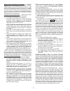
RESET TYPE 1: 4 to 20 mA (1 to 5 vdc) TEMPERATURE
RESET — Reset Type 1 is an automatic chilled water temper-
ature reset based on a remote temperature sensor input config-
ured for either an externally powered 4 to 20 mA or a 1 to
5 vdc signal. Reset Type 1 permits up to ±30 F (±16 C) of
automatic reset to the chilled water set point.
The auto, chilled water reset is hardwired to terminals
J5-3 (–) and J5-4 (+) on the CCM. Switch setting number 2 on
SW2 will determine the type of input signal. With the switch
set at the ON position the input is configured for an externally
powered 4 to 20 mA signal. With the switch in the OFF posi-
tion the input is configured for an external 1 to 5 vdc signal.
RESET TYPE 2: REMOTE TEMPERATURE RESET —
Reset Type 2 is an automatic chilled water temperature reset
based on a remote temperature sensor input signal. Reset Type
2 permits ± 30° F (± 16° C) of automatic reset to the set point
based on a temperature sensor wired to the CCM module
IMPORTANT: A field-supplied water temperature control
system for condenser water should be installed. The system
should maintain the leaving condenser water temperature
at a temperature that is 20° F (11° C) above the leaving
chilled water temperature.
The tower fan relay control is not a substitute for a con-
denser water temperature control. When used with a water
temperature control system, the tower fan relay control can
be used to help prevent low condenser water temperatures.