


71
2. Evacuate the refrigerant gas from the chiller condenser
vessel.
a. Access the PUMPDOWN LOCKOUT function
accessed from the CVC/ICVC CONTROL TEST
table to turn on the chiller water pumps. Turn the
chiller water pumps on manually if they are not
controlled by the PIC II.
b. Close pumpout unit valves 3 and 4; open valves 2
and 5.
c. Turn on the pumpout condenser water.
d. Run the pumpout compressor until the chiller
condenser pressure reaches 18 in. Hg vac (40 kPa
abs.). Monitor pressure at the CVC/ICVC and at
refrigerant gages.
e. Close valve 1b.
f. Turn off the pumpout compressor.
g. Close valves 1a, 2, and 5.
h. Turn off the pumpout condenser water.
i. Proceed to the PUMPDOWN LOCKOUT test
from the CVC/ICVC CONTROL TEST table to
turn off the chiller water pumps and lock out the
chiller compressor. Turn off the chiller water
pumps manually if they are not controlled by the
PIC II.
RETURN CHILLER TO NORMAL OPERATING
CONDITIONS
1. Ensure vessel that was opened has been evacuated.
2. Access the TERMINATE LOCKOUT function CVC/
ICVC from the CONTROL TEST table to view vessel
pressures and turn on chiller water pumps. If the chiller
water pumps are not controlled by the PIC II, turn them
on manually.
3. Open valves 1a, 1b, and 3.
4. Slowly open valve 5, gradually increasing pressure in the
evacuated vessel to 35 psig (141 kPa). Feed refrigerant
slowly to prevent tube freeze up.
5. Leak test to ensure vessel integrity.
6. Open valve 5 fully.
7. Open valve 11 to equalize the liquid refrigerant level be-
tween the vessels.
8. Close valves 1a, 1b, 3, and 5.
9. Open isolation valves 12, 13, and 14 (if present).
10. Proceed to the TERMINATE LOCKOUT screen (access-
ed from the CONTROL TEST table) to turn off the water
pumps and enable the chiller compressor for start-up. If
the chiller water pumps are not controlled by the PIC II,
turn them off manually.
GENERAL MAINTENANCE
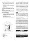
Refrigerant Properties —
The standard refrigerant for
the 19XR chiller is HFC-134a. At normal atmospheric pres-
sure, HFC-134a will boil at –14 F (–25 C) and must, therefore,
be kept in pressurized containers or storage tanks. The refriger-
ant is practically odorless when mixed with air and is noncom-
bustible at atmospheric pressure. Read the Material Safety
Data Sheet and the latest ASHRAE Safety Guide for Mechani-
cal Refrigeration to learn more about safe handling of this
refrigerant.
Adding Refrigerant —
Follow the procedures de-
scribed in Trim Refrigerant Charge section, page 72.
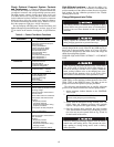
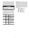
Removing Refrigerant —
If the optional pumpout sys-
tem is used, the 19XR refrigerant charge may be transferred to
a pumpout storage tank or to the chiller condenser or cooler
vessels. Follow the procedures in the Pumpout and Refrigerant
Transfer Procedures section when transferring refrigerant from
one vessel to another.
Adjusting the Refrigerant Charge —
If the addi-
tion or removal of refrigerant is required to improve chiller per-
formance, follow the procedures given under the Trim Refrig-
erant Charge section, page 72.
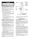
Refrigerant Leak Testing —
Because HFC-134a is
above atmospheric pressure at room temperature, leak testing
can be performed with refrigerant in the chiller. Use an elec-
tronic halide leak detector, soap bubble solution, or ultrasonic
leak detector. Ensure that the room is well ventilated and free
from concentration of refrigerant to keep false readings to a
minimum. Before making any necessary repairs to a leak,
transfer all refrigerant from the leaking vessel.
Leak Rate —
It is recommended by ASHRAE that chillers
be taken off line immediately and repaired if the refrigerant
leak rate for the entire chiller is more than 10% of the operating
refrigerant charge per year.
In addition, Carrier recommends that leaks totalling less
than the above rate but more than a rate of 0.1% of the total
charge per year should be repaired during annual maintenance
or whenever the refrigerant is transferred for other service
work.
Test After Service, Repair, or Major Leak —
If
all the refrigerant has been lost or if the chiller has been opened
for service, the chiller or the affected vessels must be pressure
tested and leak tested. Refer to the Leak Test Chiller section to
perform a leak test.
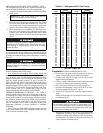
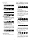
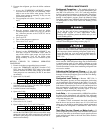
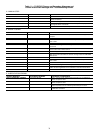
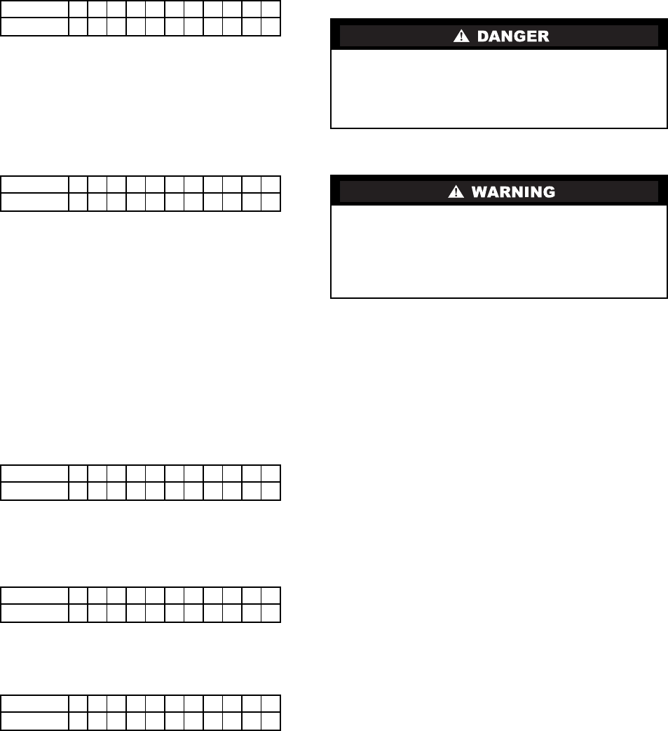
VALVE 1a 1b 2 3 4 5 8 11 12 13 14
CONDITION
CC CCCCC
VALVE 1a 1b 2 3 4 5 8 11 12 13 14
CONDITION
CCCCCCCCCCC
VALVE 1a 1b 2 3 4 5 8 11 12 13 14
CONDITION
C CCCCCCC
VALVE 1a 1b 2 3 4 5 8 11 12 13 14
CONDITION
C C CCCCC
VALVE 1a 1b 2 3 4 5 8 11 12 13 14
CONDITION
CCCCCCC
HFC-134a will dissolve oil and some nonmetallic materi-
als, dry the skin, and, in heavy concentrations, may dis-
place enough oxygen to cause asphyxiation. When
handling this refrigerant, protect the hands and eyes and
avoid breathing fumes.
Always use the compressor pumpdown function in the
Control Test table to turn on the cooler pump and lock out
the compressor when transferring refrigerant. Liquid refrig-
erant may flash into a gas and cause possible freeze-up
when the chiller pressure is below 30 psig (207 kPa) for
HFC-134a.