


69
Chillers with Storage Tanks —
If the chiller has iso-
lation valves, leave them open for the following procedures.
The letter “C” describes a closed valve. See Fig. 17, 18, 29,
and 30.
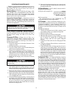
TRANSFER REFRIGERANT FROM PUMPOUT STOR-
AGE TANK TO CHILLER
1. Equalize refrigerant pressure.
a. Use the PIC II terminate lockout function on the
PUMPDOWN LOCKOUT screen, accessed from
the CONTROL TEST table to turn on the water
pumps and monitor pressures.
b. Close pumpout unit valves 2, 4, 5, 8, and 10, and
close chiller charging valve 7; open chiller isola-
tion valves 11, 12, 13, and 14 (if present).
c. Open pumpout unit/storage tank valves 3 and 6,
open chiller valves 1a and 1b.
d. Slowly open valve 5 to increase chiller pressure to
68 psig 35 psig (141 kPa) for HFC-134a. Feed
refrigerant slowly to prevent freeze up.
e. Open valve 5 fully after the pressure rises above
the freeze point of the refrigerant. Open liquid line
valves 7 and 10 until refrigerant pressure
equalizes.
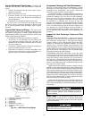
2. Transfer the remaining refrigerant.
a. Close valve 5 and open valve 4.
b. Turn off the chiller water pumps using the CVC/
ICVC (or manually, if necessary).
c. Turn off the pumpout condenser water, and turn on
the pumpout compressor to push liquid out of the
storage tank.
d. Close liquid line valve 7.
e. Turn off the pumpout compressor.
f. Close valves 3 and 4.
g. Open valves 2 and 5.
h. Turn on the pumpout condenser water.
i. Run the pumpout compressor until the pumpout
storage tank pressure reaches 5 psig (34 kPa)
(18 in. Hg [40 kPa absolute] if repairing the tank).
j. Turn off the pumpout compressor.
k. Close valves 1a, 1b, 2, 5, 6, and 10.
l. Turn off pumpout condenser water.
If the chilled water and condenser water pumps are not
controlled by the PIC II, these pumps must be started and
stopped manually at the appropriate times during the refrig-
erant transfer procedure.
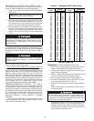
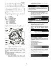
VALVE 1a 1b 2 3 4 5 6 7 8 10 11 12 13 14
CONDITION
CCCCCC
Follow Steps d and e carefully to prevent damage from
freeze-up.
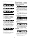
VALVE 1a 1b 2 3 4 5 6 7 8 10 11 12 13 14
CONDITION
CC C
VALVE 1a 1b 2 3 4 5 6 7 8 10 11 12 13 14
CONDITION
CCC
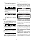
VALVE 1a 1b 2 3 4 5 6 7 8 10 11 12 13 14
CONDITION
CC CC
VALVE 1a 1b 2 3 4 5 6 7 8 10 11 12 13 14
CONDITION
CCCCCCCCCC
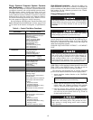
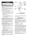
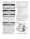
OIL RETURN
LINE
CONNECTION
CONDENSER
WATER
CONNECTIONS
REFRIGERANT
INLET VALVE
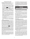
LEGEND
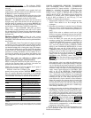
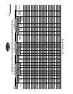
*Bimetal thermal protector imbedded in motor winding.
Fig. 35 — 19XR Pumpout Unit Wiring Schematic
C — Contactor
FU — Fuse, 3 Amps
HP — High-Pressure Cutout
OL — Compressor Overload
T’STAT
—
Internal Thermostat
Compressor Terminal
Contactor Terminal
Overload Terminal
Pumpout Unit Terminal
Fig. 36 — Optional Pumpout Unit