


106
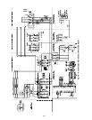
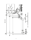
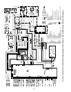
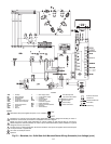
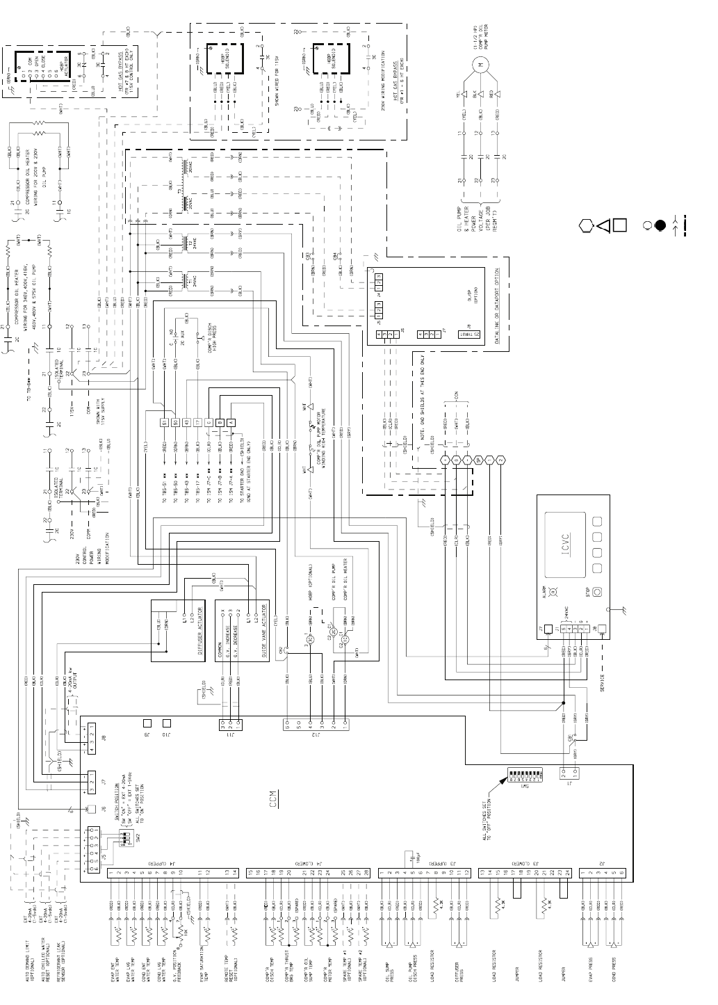
LEGEND
AUX — Auxiliary
BRG — Bearing
C — Contactor
CB — Circuit Breaker
CCM — Chiller Control Module
CCN — Carrier Comfort Network
COMP’R — Compressor
COND — Condenser
DISCH — Discharge
DL/DP — Datalink or Dataport
ENT — Entering
EVAP — Evaporator
EXT — External
FR — Frame
GND — Ground
G.V. — Guide Vane
HGBP — Hot Gas Bypass
HT EXCH — Heat Exchanger
ICVC — International Chiller Visual Controller
ISM — Integrated Starter Module
LEGEND (cont)
L — Main Supply Power
LVG — Leaving
N.O. — Normally Open
PRESS — Pressure
REQM’T — Requirement
TEMP — Temperature
TB — Terminal Board
Denotes Control Panel Terminal
Denotes Oil Pump Terminal
Denotes Power Panel Terminal
** Denotes Motor Starter Panel Conn.
Denotes Component Terminal
Wire Splice
Denotes Conductor Male/Female Connector
Option Wiring
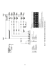
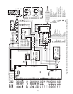
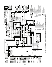
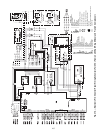
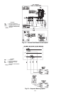
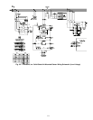
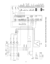
Fig. 47B — Electronic PIC II Control Panel Wiring Schematic For ICVC (Frame 4 with Split Ring Diffuser and Frame 5 Compressor)