50
Leak Test Chiller —
Due to regulations regarding refrig-
erant emissions and the difficulties associated with separating
contaminants from the refrigerant, Carrier recommends the
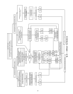
following leak test procedure. See Fig. 28 for an outline of the
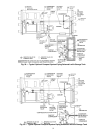
leak test procedure. Refer to Fig. 29 and 30 during pumpout
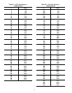
procedures and Tables 5A and 5B for refrigerant pressure/
temperature values.
1. If the pressure readings are normal for the chiller
condition:
a. Evacuate the holding charge from the vessels, if
present.
b. Raise the chiller pressure, if necessary, by adding
refrigerant until pressure is at the equivalent satu-
rated pressure for the surrounding temperature.
Follow the pumpout procedures in the Transfer
Refrigerant from Pumpout Storage Tank to Chiller
section, Steps 1a - e, page 69.
c. Leak test chiller as outlined in Steps 3 - 9.
2. If the pressure readings are abnormal for the chiller
condition:
a. Prepare to leak test chillers shipped with refriger-
ant (Step 2h).
b. Check for large leaks by connecting a nitrogen bottle
and raising the pressure to 30 psig (207 kPa). Soap
test all joints. If the test pressure holds for 30 minutes,
prepare the test for small leaks (Steps 2g - h).
c. Plainly mark any leaks that are found.
d. Release the pressure in the system.
e. Repair all leaks.
f. Retest the joints that were repaired.
g. After successfully completing the test for large
leaks, remove as much nitrogen, air, and moisture
as possible, given the fact that small leaks may be
present in the system. This can be accomplished by
following the dehydration procedure, outlined in
the Chiller Dehydration section, page 53.
h. Slowly raise the system pressure to a maximum of
160 psig (1103 kPa) but no less than 35 psig
(241 kPa) for HFC-134a by adding refrigerant.
Proceed with the test for small leaks (Steps 3-9).
3. Check the chiller carefully with an electronic leak detec-
tor, halide torch, or soap bubble solution.
4. Leak Determination — If an electronic leak detector indi-
cates a leak, use a soap bubble solution, if possible, to
confirm. Total all leak rates for the entire chiller. Leakage
at rates greater than 1 lb./year (0.45 kg/year) for the entire
chiller must be repaired. Note the total chiller leak rate on
the start-up report.
5. If no leak is found during the initial start-up procedures,
complete the transfer of refrigerant gas from the pumpout
storage tank to the chiller (see Transfer Refrigerant from
Pumpout Storage Tank to Chiller section, page 69). Re-
test for leaks.
6. If no leak is found after a retest:
a. Transfer the refrigerant to the pumpout storage
tank and perform a standing vacuum test as out-
lined in the Standing Vacuum Test section, below.
b. If the chiller fails the standing vacuum test, check
for large leaks (Step 2b).
c. If the chiller passes the standing vacuum test,
dehydrate the chiller. Follow the procedure in
the Chiller Dehydration section. Charge the chiller
with refrigerant (see Transfer Refrigerant from
Pumpout Storage Tank to Chiller section,
page 69).
7. If a leak is found after a retest, pump the refrigerant back
into the pumpout storage tank or, if isolation valves are
present, pump the refrigerant into the non-leaking
vessel (see Pumpout and Refrigerant Transfer procedures
section).
8. Transfer the refrigerant until the chiller pressure is at
18 in. Hg (40 kPa absolute).
9. Repair the leak and repeat the procedure, beginning from
Step 2h, to ensure a leak-tight repair. (If the chiller is
opened to the atmosphere for an extended period, evacu-
ate it before repeating the leak test.)
Standing Vacuum Test —
When performing the
standing vacuum test or chiller dehydration, use a manometer
or a wet bulb indicator. Dial gages cannot indicate the small
amount of acceptable leakage during a short period of time.
1. Attach an absolute pressure manometer or wet bulb indi-
cator to the chiller.
2. Evacuate the vessel (see Pumpout and Refrigerant Trans-
fer Procedures section, page 67) to at least 18 in. Hg vac,
ref 30-in. bar (41 kPa), using a vacuum pump or the
pump out unit.
3. Valve off the pump to hold the vacuum and record the
manometer or indicator reading.
4. a. If the leakage rate is less than 0.05 in. Hg (0.17 kPa
) in
24 hours, the chiller is sufficiently tight.
b. If the leakage rate exceeds 0.05 in. Hg (0.17 kPa)
in
24 hours, repressurize the vessel and test for leaks.
If refrigerant is available in the other vessel, pressur-
ize by following Steps 2-10 of Return Chiller To
Normal Operating Conditions section, page 71. If
not, use nitrogen and a refrigerant tracer. Raise the
vessel pressure in increments until the leak is
detected. If refrigerant is used, the maximum gas
pressure is approximately 70 psig (483 kPa) for
HFC-134a at normal ambient temperature. If nitro-
gen is used, limit the leak test pressure to 230 psig
(1585 kPa) maximum.
5. Repair the leak, retest, and proceed with dehydration.
Never charge liquid refrigerant into the chiller if the pres-
sure in the chiller is less than 35 psig (241 kPa) for
HFC-134a. Charge as a gas only, with the cooler and con-
denser pumps running, until this pressure is reached, using
PUMPDOWN LOCKOUT and TERMINATE LOCK-
OUT mode on the PIC II. Flashing of liquid refrigerant at
low pressures can cause tube freeze-up and considerable
damage.


