


112
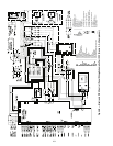
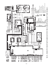
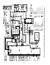
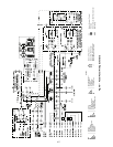
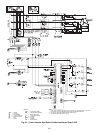
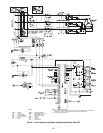
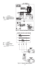
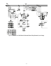
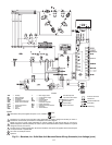
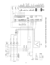
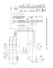
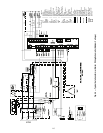
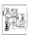
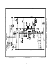
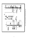
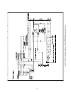
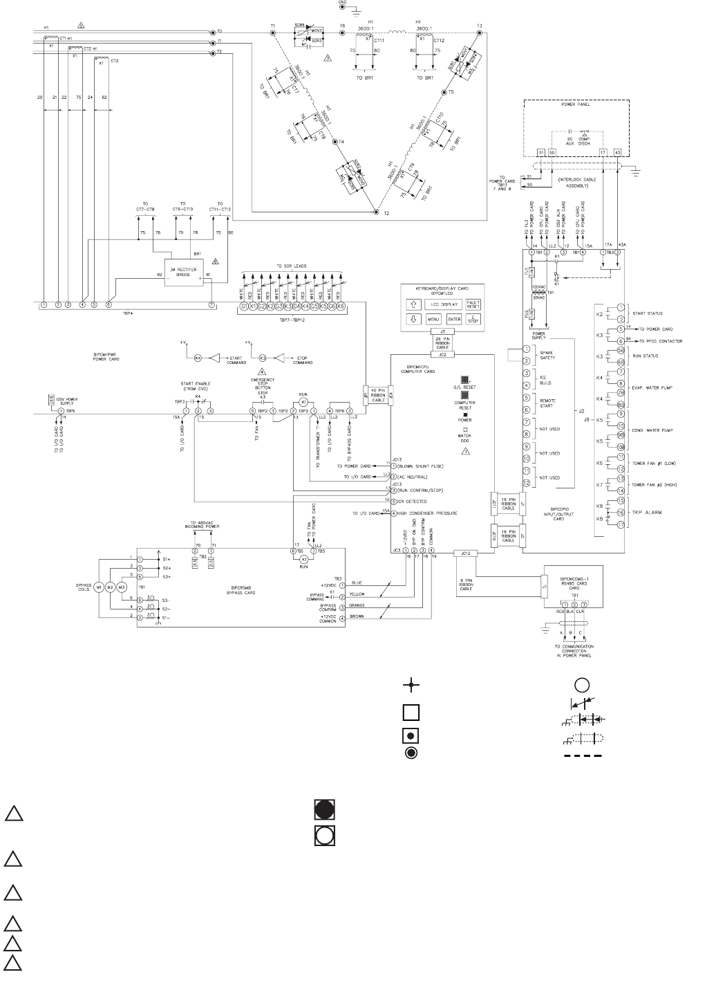
Fig. 53 — Benshaw, Inc. Solid-State Unit Mounted Starter Wiring Schematic (Low Voltage) (cont)
AUX — Auxiliary
BR — Bridge Rectifier
CB — Circuit Breaker
COND — Condenser
CPU — Central Processing Unit
CVC/
ICVC
—
Chiller Visual Controller
CT — Current Transformer
EVAP — Evaporator
FU — Fuse
GND — Ground
L — Main Supply Power
LL — Control Power Supply
M — Contactor
O/L — Overload Reset
PFCC — Power Factor
Correction Capacitor
RLA — Rated Load Amps
SCR — Silicone Controller Rectifier
ST — Shunt Trip
TB — Terminal Block
Wire Node Symbol
may have terminal block
Benshaw supplied
terminal block
Terminal Strip
Power Connection
PC Board Terminals
Twisted Pair
Twisted Shielded Pair
Shield Wire
Field Wiring
LEGEND
NOTES:
LED status with power applied and prior to run command.
Transformer T1 primary fuses FU1/FU2 value dependent on system voltage and model, per Chart 1.
Transformer connections per transformer nameplate connection diagram.
MOVs are used on power stack assemblies for system voltages of 200 through 460 vac (as shown).
Resistor/capacitor networks (DVDTs) are used on power stack assemblies in place of MOVs for a system
voltage of 575 vac (not shown).
K3 relay shown in deenergized state. K3 contact will close when power is supplied. K3 contact will open
on stop command or system fault.
CT1-CT3 are sized per Chart 2.
Optional.
1
"ON"
"OFF"
2
3
4
5
6