


58
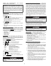
VERIFY VFD CONFIGURATION AND CHANGE
PARAMETERS IF NECESSARY
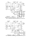
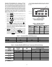
Using the Keypad
— The keypad display is used to monitor,
view fault history and adjust the program of the VFD
microprocessor. It operates in two modes: Monitor mode and
Program mode:
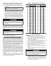
Use the and keys to:
• Step through the drive parameter menus and error log
when the keypad/display is in Program mode.
• Increase or decrease a numeric value such as the refer-
ence or parameter value.
• Hold down these keys to increase the scroll speed.
Use the softkey to:
• Display a parameter or a selection value in Program
mode.
• Save a value.
• Move through each monitor display item when in Moni-
tor mode.
Monitor Mode (Default Mode)
— Specific drive conditions
may be monitored on the keypad when in this mode. An LED
will be illuminated next to the description of what is displayed
on the keypad. Use the softkey to scroll through and
monitor the following selections:
• All LEDs on — Speed request from the CVC/ICVC
• Motor Speed
• Output Frequency
• Output Voltage
• Output Current
Program Mode
— This mode displays and modifies the con-
figuration parameters of the VFD microprocessor. Particular
parameters, parameter numbers, and error log information can
be displayed when in Program mode.
Press the softkey until the PROGRAM LED is
illuminated to enter the Program mode.
Use the and keys to move through the menus
Press softkey to select the desired menu.
Press and keys to move through following parameters.
*Vector control is not used in this configuration.
Press softkey to select a parameter menu screen.
Press and keys to adjust the selected parameter.
Press the softkey until the PROGRAM LED
turns off to exit the program.
Accessing Password Protected Parameters
— Although the
VFD controller has been preconfigured as the factory, the user
will need to be able to access the parameters to verify the job
specific parameters are correct, tune the controller or correct a
problem. The two passwords protecting the VFD configuration
are Parameter Set Display password and Program Disable
password. The Parameter Set Display password restricts view-
ing. P.nnn parameters above 007 and all H.nnn and R.nnn
screens. The password can be accessed at parameter P.006 and
will switch between enabled and disabled each time the pass-
word 107 is entered. The Program Disable password restricts
the changing of the drive parameter set. To enable or disable
changes select parameter P.051 and enter the password 26.
NOTE: Some of the parameters can be changed only when the
drive is stopped.
See the Initial Start-Up Checklist section for VFD Job Specific
Configuration table. For job specific parameters see inside of
the VFD enclosure door, next to the keypad. Refer to the VFD
Configuration table for the entire list of parameters.
VFD CHILLER FIELD SET UP AND VERIFICATION
Label Locations
— Verify the following labels have been
installed properly and match the chiller requisition:
• Surge parameters — Located inside the control panel.
• Chiller identification nameplate — Located on the right
side of the control panel.
• VFD Parameter — Located to the right of the VFD con-
troller keypad on the VFD module.
• VFD Nameplate — Located on the right side of the VFD
as viewed from its front.
• Record all nameplate information on the Reliance Con-
figuration sheet.
Drive Protection and Other Incoming Wiring
1. Verify that the branch disconnects or other local discon-
nects are open and properly tagged out.
2. Verify that the branch circuit protection and AC input
wiring to the VFD are in accordance with NEC/CEC
(National Electrical Code/California Energy Commis-
sion) and all other local codes.
3. Verify that the fuses are per the field wiring diagram.
4. Verify that the incoming source does not exceed 85 kA.
5. Verify the power lugs in the VFD and branch protection
are properly secured. Inspect the ground cable and ensure
it is properly connected at the branch and to the ground
lug in the VFD.
6. Verify the conduit for the power wiring in securely con-
nected to the VFD flanged cover and runs continuously to
the branch protection.
7. Verify that the incoming and outgoing wires have been
properly connected inside of the reactor enclosure if a
separate line reactor has been added to the chiller.
8. Ensure the control and signal wires connected to the chill-
er controller or the VFD are in separate conduit.
IMPORTANT: The VFD controller has been factory con-
figured for use and communications to the Chiller Visual
Controller/International Chiller Visual Controller (CVC/
ICVC). Some parameters are specific to the chiller config-
uration and will need to be verified prior to operation.
Speed control and starting the drive have been disabled at
the VFD keypad. All command functions must be initiated
from the CVC/ICVC.
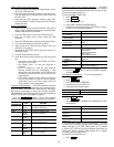
P.nnn — General Parameters
U.nnn — Vector Control Parameters*
H.nnn — Volts/Hertz Control Parameters
R.nnn — RMI Remote Monitor Interface
Parameters
E.nnn — Error Log (See fault codes)
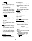
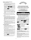
Changing parameters may adversely affect chiller
operation.
↑ ↓
ENTER
ENTER
PROGRAM
↑ ↓
ENTER
↑ ↓
ENTER
↑ ↓
PROGRAM
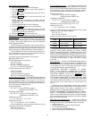
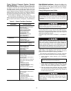
It is the operator’s responsibility to distribute access to the
passwords. Carrier is not responsible for unauthorized
access violations within the operator’s organization. Failure
to observe this warning could result in bodily injury.
Restoring the default parameter P.050 will require all the
Carrier default parameters to be restored manually.