


48
BEFORE INITIAL START-UP
Job Data Required
• list of applicable design temperatures and pressures
(product data submittal)
• chiller certified prints
• starting equipment details and wiring diagrams
• diagrams and instructions for special controls or options
• 19XR Installation Instructions
• pumpout unit instructions
Equipment Required
• mechanic’s tools (refrigeration)
• digital volt-ohmmeter (DVM)
• clamp-on ammeter
• electronic leak detector
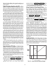
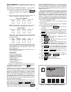
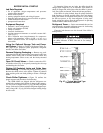
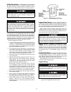
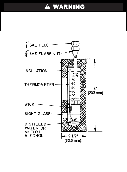
• absolute pressure manometer or wet-bulb vacuum indi-
cator (Fig. 27)
• 500-v insulation tester (megohmmeter) for compressor
motors with nameplate voltage of 600 v or less, or a
5000-v insulation tester for compressor motor rated
above 600 v
Using the Optional Storage Tank and Pump-
out System —
Refer to Chillers with Storage Tanks sec-
tion, page 69 for pumpout system preparation, refrigerant
transfer, and chiller evacuation.
Remove Shipping Packaging —
Remove any pack-
aging material from the control center, power panel, guide vane
actuator, motor cooling and oil reclaim solenoids, motor and
bearing temperature sensor covers, and the factory-mounted
starter.
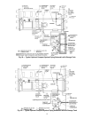
Open Oil Circuit Valves —
Check to ensure the oil fil-
ter isolation valves (Fig. 4) are open by removing the valve cap
and checking the valve stem.
Tighten All Gasketed Joints and Guide Vane
Shaft Packing —
Gaskets and packing normally relax by
the time the chiller arrives at the jobsite. Tighten all gasketed
joints and the guide vane shaft packing to ensure a leak-tight
chiller.
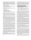
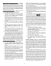
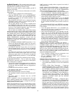
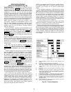
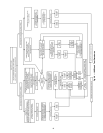
Check Chiller Tightness —
Figure 28 outlines the
proper sequence and procedures for leak testing.
The 19XR chillers are shipped with the refrigerant con-
tained in the condenser shell and the oil charge in the compres-
sor. The cooler is shipped with a 15 psig (103 kPa) refrigerant
charge. Units may be ordered with the refrigerant shipped sepa-
rately, along with a 15 psig (103 kPa) nitrogen-holding charge
in each vessel.
To determine if there are any leaks, the chiller should be
charged with refrigerant. Use an electronic leak detector to
check all flanges and solder joints after the chiller is pressur-
ized. If any leaks are detected, follow the leak test procedure.
If the chiller is spring isolated, keep all springs blocked in
both directions to prevent possible piping stress and damage
during the transfer of refrigerant from vessel to vessel during
the leak test process, or any time refrigerant is being trans-
ferred. Adjust the springs when the refrigerant is in operating
condition and the water circuits are full.
Refrigerant Tracer —
Carrier recommends the use of an
environmentally acceptable refrigerant tracer for leak testing
with an electronic detector or halide torch.
Ultrasonic leak detectors can also be used if the chiller is
under pressure.
Do not use air or oxygen as a means of pressurizing
the chiller. Mixtures of HFC-134a and air can undergo
combustion.
Fig. 27 — Typical Wet-Bulb Type
Vacuum Indicator