


39
(see wiring diagrams or certified drawings). The temperature
sensor must be wired to terminal J4-13 and J4-14. To configure
Reset Type 2, enter the temperature of the remote sensor at the
point where no temperature reset will occur (REMOTE TEMP
–> NO RESET). Next, enter the temperature at which the full
amount of reset will occur (REMOTE TEMP –> FULL
RESET). Then, enter the maximum amount of reset required to
operate the chiller (DEGREES RESET). Reset Type 2 can now
be activated.
RESET TYPE 3 — Reset Type 3 is an automatic chilled water
temperature reset based on cooler temperature difference.
Reset Type 3 adds ± 30° F (± 16° C) based on the temperature
difference between the entering and leaving chilled water
temperature.
To configure Reset Type 3, enter the chilled water tempera-
ture difference (the difference between entering and leaving
chilled water) at which no temperature reset occurs (CHW
DELTA T –> NO RESET). This chilled water temperature dif-
ference is usually the full design load temperature difference.
Next, enter the difference in chilled water temperature at which
the full amount of reset occurs (CHW DELTA T –> FULL RE-
SET). Finally, enter the amount of reset (DEGREES RESET).
Reset Type 3 can now be activated.
Demand Limit Control Option —
The demand limit
control option (20 mA DEMAND LIMIT OPT) is externally
controlled by a 4 to 20 mA or 1 to 5 vdc signal from an energy
management system (EMS). The option is set up on the
RAMP_DEM screen. When enabled, 4 mA is the 100% de-
mand set point with an operator-configured minimum demand
at a 20 mA set point (DEMAND LIMIT AT 20 mA).
The auto. demand limit is hardwired to terminals J5-1 (–)
and J5-2 (+) on the CCM. Switch setting number 1 on SW2
will determine the type of input signal. With the switch set at
the ON position the input is configured for an externally pow-
ered 4 to 20 mA signal. With the switch in the OFF position the
input is configured for an external 1 to 5 vdc signal.
Surge Prevention Algorithm (Fixed Speed
Chiller) —
This is an operator-configurable feature that can
determine if lift conditions are too high for the compressor and
then take corrective action. Lift is defined as the difference be-
tween the pressure at the impeller eye and at the impeller
discharge. The maximum lift a particular impeller wheel can
perform varies with the gas flow across the impeller and the
size of the wheel.
A surge condition occurs when the lift becomes so high the
gas flow across the impeller reverses. This condition can even-
tually cause chiller damage. The surge prevention algorithm
notifies the operator that chiller operating conditions are mar-
ginal and to take action to help prevent chiller damage such as
lowering entering condenser water temperature.
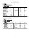
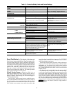
The surge prevention algorithm first determines if correc-
tive action is necessary. The algorithm checks 2 sets of opera-
tor-configured data points, the minimum load points (MIN.
LOAD POINT [T1,P1]) and the full load points (FULL LOAD
POINT [T2,P2]). These points have default settings as defined
on the OPTIONS screen or on Table 4.
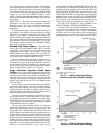
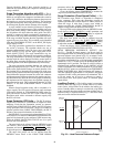
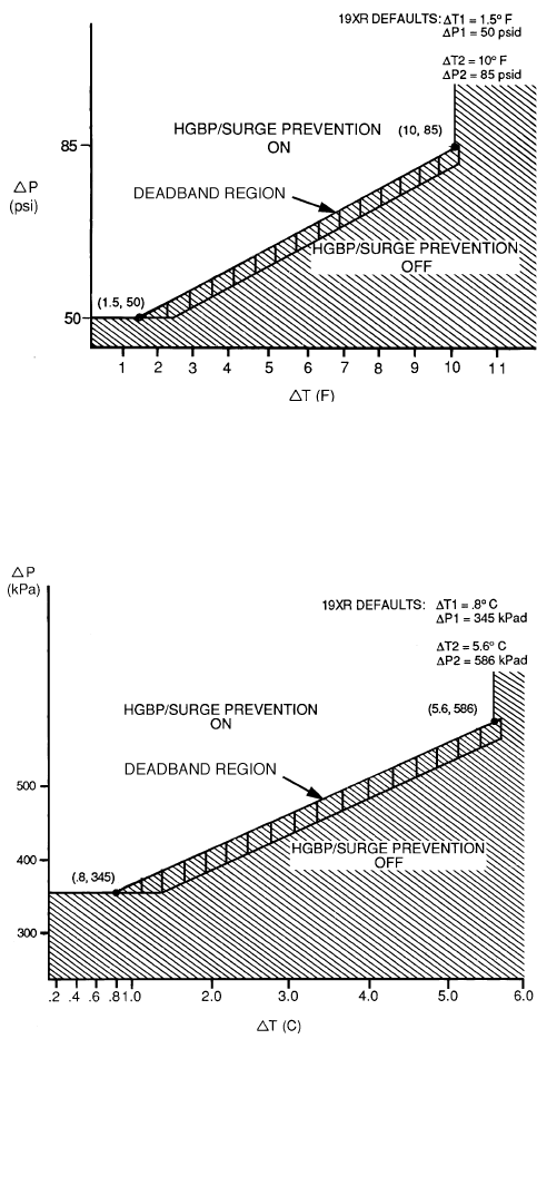
The surge prevention algorithm function and settings are
graphically displayed in Fig. 21 and 22. The two sets of load
points on the graph (default settings are shown) describe a line
the algorithm uses to determine the maximum lift of the com-
pressor. When the actual differential pressure between the cool-
er and condenser and the temperature difference between the
entering and leaving chilled water are above the line on the
graph (as defined by the minimum and full load points), the al-
gorithm goes into a corrective action mode. If the actual values
are below the line and outside of the deadband region, the algo-
rithm takes no action. When the point defined by the ACTIVE
DELTA P and ACTIVE DELTA T, moves from the region
where the HOT GAS BYPASS/SURGE PREVENTION is off,
the point must pass through the deadband region to the line
determined by the configured values before the HOT GAS
BYPASS/SURGE PREVENTION will be turned on. As the
point moves from the region where the HOT GAS BYPASS/
SURGE PREVENTION is on, the point must pass through the
deadband region before the HOT GAS BYPASS/SURGE
PREVENTION is turned off. Information on modifying the de-
fault set points of the minimum and full load points may be
found in the Input Service Configurations section, page 55.
The state of the surge/hot gas bypass algorithm on the
HEAT_EX DISPLAY SCREEN (Surge/HGBP Active?).
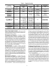
Corrective action can be taken by making one of 2 choices.
If a hot gas bypass line is present and the hot gas option is
selected on the OPTIONS table (SURGE LIMIT/HGBP
OPTION is set to 1), the hot gas bypass valve can be energized.
If the hot gas bypass option is not selected (SURGE LIMIT/
HGBP OPTION is set to 0), hold the guide vanes. See Table 4,
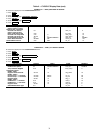
LEGEND
∆P = (Condenser Psi) – (Cooler Psi)
∆T = (ECW) – (LCW)
Fig. 21 — 19XR Hot Gas Bypass/Surge
Prevention with Default English Settings
ECW — Entering Chilled Water
HGBP — Hot Gas Bypass
LCW — Leaving Chilled Water
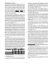
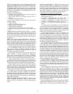
LEGEND
∆P = (Condenser kPa) – (Cooler kPa)
∆T = (ECW) – (LCW)
Fig. 22 — 19XR Hot Gas Bypass/Surge
Prevention with Default Metric Settings
ECW — Entering Chilled Water
HGBP — Hot Gas Bypass
LCW — Leaving Chilled Water