


77
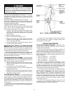
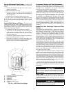
TRANSDUCER REPLACEMENT — Since the transducers
are mounted on Schrader-type fittings, there is no need to re-
move refrigerant from the vessel when replacing the transduc-
ers. Disconnect the transducer wiring. Do not pull on the trans-
ducer wires. Unscrew the transducer from the Schrader fitting.
When installing a new transducer, do not use pipe sealer
(which can plug the sensor). Put the plug connector back on the
sensor and snap into place. Check for refrigerant leaks.
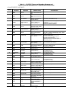
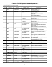
Control Algorithms Checkout Procedure —
One
of the tables on the CVC/ICVC SERVICE menu is CON-
TROL ALGORITHM STATUS. The maintenance screens
may be viewed from the CONTROL ALGORITHM STATUS
table to see how a particular control algorithm is operating.
These maintenance screens are very useful in helping to de-
termine how the control temperature is calculated and guide
vane positioned and for observing the reactions from load
changes, control point overrides, hot gas bypass, surge preven-
tion, etc. The tables are:
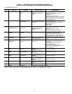
Control Test —
The Control Test feature can check all the
thermistor temperature sensors, pressure transducers, pumps
and their associated flow devices, the guide vane actuator, and
other control outputs such as hot gas bypass. The tests can help
to determine whether a switch is defective or a pump relay is
not operating, as well as other useful troubleshooting issues.
During pumpdown operations, the pumps are energized to pre-
vent freeze-up and the vessel pressures and temperatures are
displayed. The Pumpdown/Lockout feature prevents compres-
sor start-up when there is no refrigerant in the chiller or if the
vessels are isolated. The Terminate Lockout feature ends the
Pumpdown/Lockout after the pumpdown procedure is reversed
and refrigerant is added.
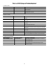
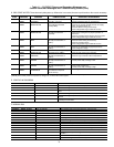
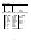
LEGEND TO TABLES 11A-11J
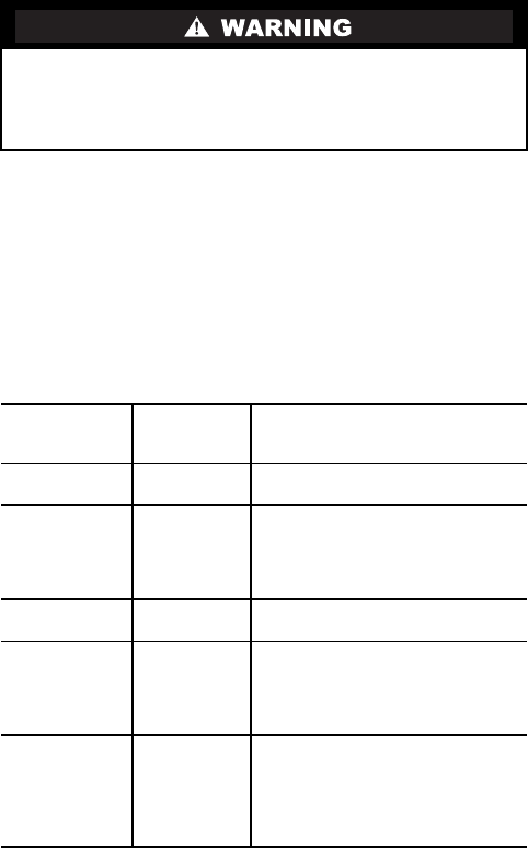
Be sure to use a back-up wrench on the Schrader fitting
whenever removing a transducer, since the Schrader fitting
may back out with the transducer, causing a large leak and
possible injury to personnel.
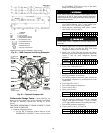
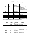
CAPACITY Capacity
Control
This table shows all values used
to calculate the chilled water/brine
control point.
OVERRIDE Override
Status
Details of all chilled water control
override values.
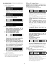
HEAT_EX Surge/
HGBP
Status
The surge and hot gas bypass
control algorithm status is viewed
from this screen. All
values dealing with this control
are displayed.
LL_MAINT LEAD/LAG
Status
Indicates LEAD/LAG operation
status.
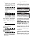
OCCDEFCM Time
Schedules
Status
The Local and CCN occupied
schedules are displayed here to
help the operator quickly deter-
mine whether the schedule is in
the “occupied” mode or not.
WSMDEFME Water
System
Manager
Status
The water system manager is a
CCN module that can turn on the
chiller and change the chilled
water control point. This screen
indicates the
status of this system.
CCM — Chiller Control Module
CVC — Chiller Visual Controller
CHW — Chilled Water
ICVC —
International Chiller Visual
Control
ISM — Integrated Starter Module
PIC II — Product Integrated Controls II
VFD — Variable Frequency Drive