122
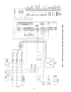
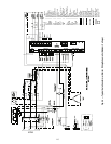
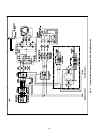
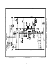
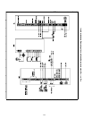
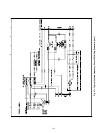
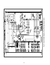
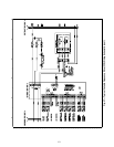
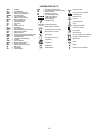
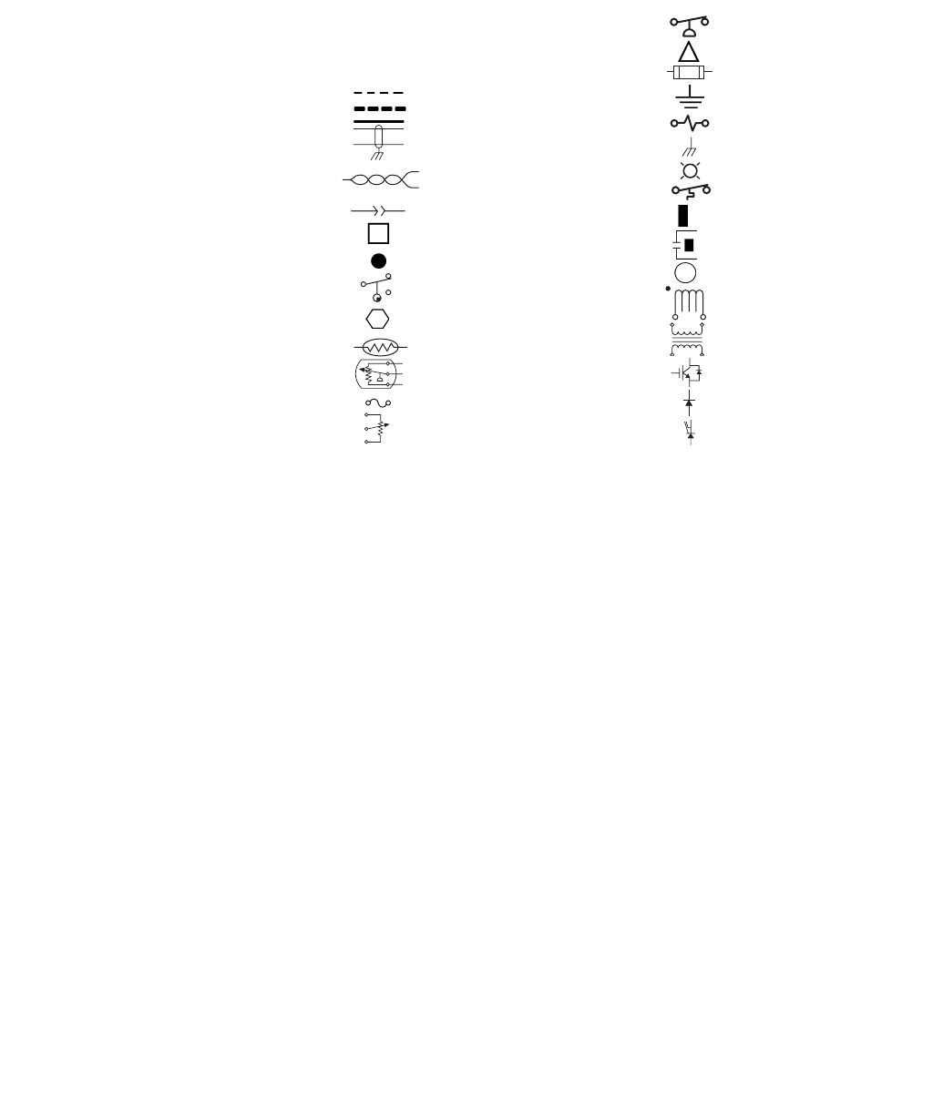
LEGEND FOR FIG. 57
AUX — Auxiliary
CB — Circuit Breaker
CCM — Chiller Control Module
CCN — Carrier Comfort Network
COMM — Communications
CT — Current Transformer
CVC — Chiller Visual Controller
DP/DL — Data Port/Data Link
DS — Disconnect Switch
FD — Fused Disconnect
FR — Fan Relay
FU — Fuse
G — Chassis Ground
GV — Guide Vane
HGBP — Hot Gas Bypass
HPR — High Discharge Pressure Relay
HPS — High Pressure Switch
HX — Heat Exchanger
ICVC — International Chiller Visual Controller
IGBT — Insulated Gate Bipolar Transistor
IGV — Inlet Guide Vane
ISM — Integrated Starter Module
J — Junction
LEM — Current Detector
MAB — Module Adapter Board
RC — Regulator Controller
RMI — Remote Metering Interface
ST — Shunt Trip
T — Transformer
TB — Terminal Block
VFD — Variable Frequency Drive
1C — Compressor Oil Heater Contactor
1M — Start Contactor
2C — Oil Pump Contactor
3C — Hot Gas Bypass Relay
Field Control Wiring
Field Power Wiring
Factory Wiring
Shielded Cable
Twisted Pair Wiring
Male/Female Connector
Terminal Block Connection
Wire Splice or Junction
Cam Switch
Component Terminal
Thermistor
Transducer
Fusible Link
Potentiometer
-
+
Pressure Switch
Compr Oil Pump Terminal
Cartridge Fuse
Earth Ground
Resistor
Chassis Ground
Light
Temperature Switch
Common Potential
Dry Contact
VFD Terminal
Current Transformer, Polarized
(Direction Determined by •)
Transformer
IGBT
Diode
Silicone Control Rectifier


