


98
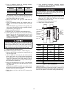
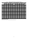
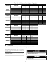
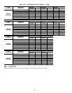
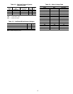
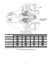
Compressor Assembly Torques
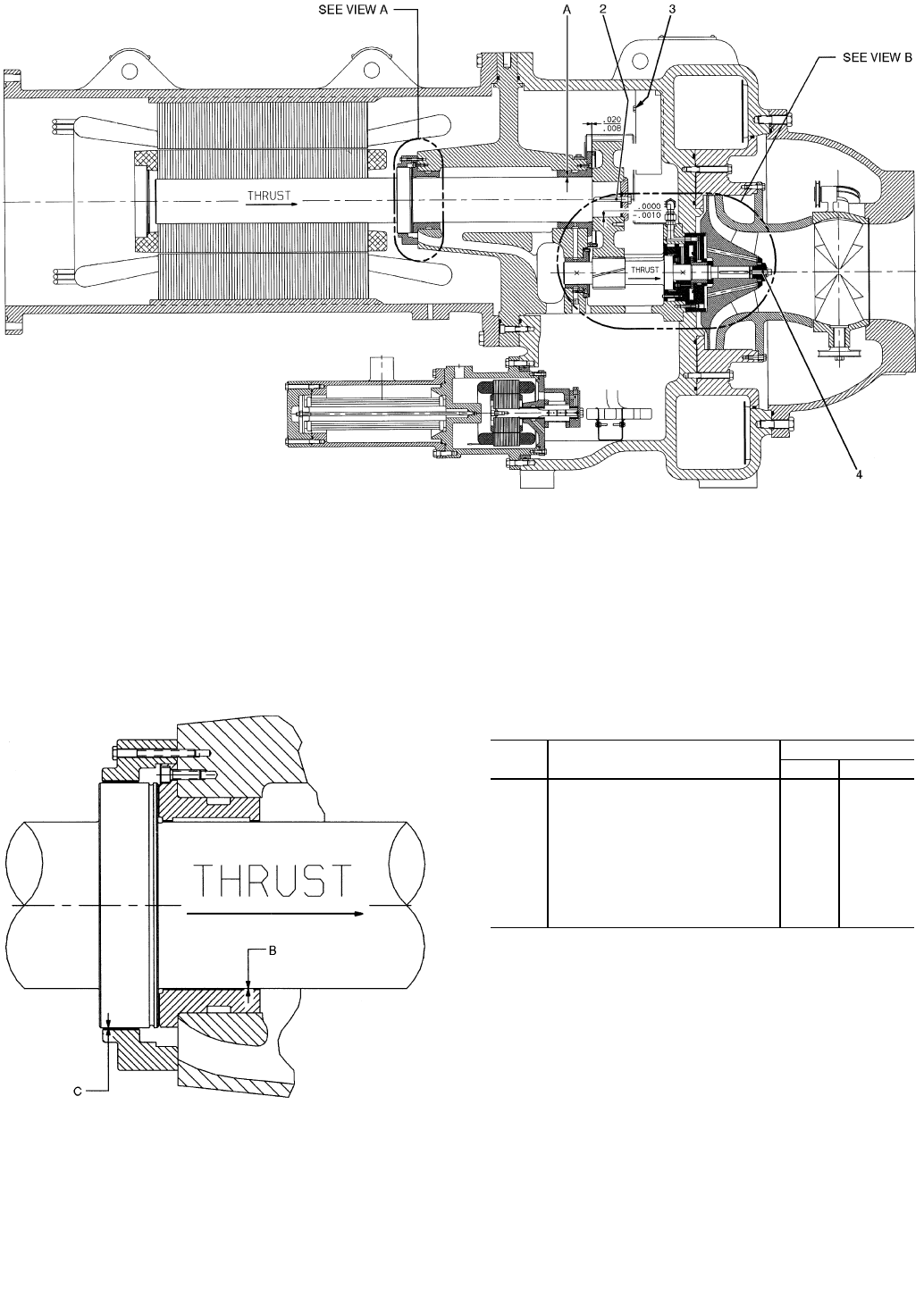
LEGEND
*Not shown.
NOTES:
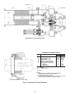
1. All clearances for cylindrical surfaces are diametrical.
2. Dimensions are with rotor in thrust position.
3. Dimensions shown are in inches.
4. Impeller spacing should be performed in accordance with most
recent Carrier Service Bulletin on impeller spacing.
ITEM DESCRIPTION
TORQUE
ft.-lb N•m
1* Oil Heater Retaining Nut 20 28
2 Bull Gear Retaining Bolt 80-85 108-115
3 Demister Bolts 15-19 20-26
4 Impeller Retaining Bolt 44-46 60-62
5* Motor Terminals (Low Voltage) 50 68
6* Guide Vane Shaft Seal Nut 25 34
7* Motor Terminals (High Voltage)
— Insulator 2-4 2.7-5.4
— Packing Nut 5 6.8
— Brass Jam Nut 10 13.6
N•m — Newton meters
VIEW A
LOW SPEED SHAFT THRUST DISK
Fig. 44 — Compressor Fits and Clearances
COMPRESSOR, TRANSMISSION AREA