44
stop the chiller when a specific time period on the ice
build schedule is not set for ice build.
4. Entering Chilled Water Temperature and ICE BUILD
Contacts — Compressor operation terminates when the
ICE BUILD TERMINATION parameter is set to
2 (BOTH) and the conditions described above in items
2 and 3 for entering chilled water temperature and remote
contacts have occurred.
NOTE: It is not possible to override the CHILLER START/
STOP, CONTROL POINT, and ACTIVE DEMAND LIMIT
variables from CCN devices (with a priority 4 or greater) dur-
ing the ice build period. However, a CCN device can override
these settings during 2-chiller lead/lag operation.
RETURN TO NON-ICE BUILD OPERATIONS — The ice
build function forces the chiller to start, even if all other sched-
ules indicate that the chiller should stop. When the ice build
function terminates, the chiller returns to normal temperature
control and start/stop schedule operation. The CHILLER
START/STOP and CONTROL POINT return to normal opera-
tion. If the CHILLER START/STOP or CONTROL POINT has
been forced (with a device of less than 4 priority) before the ice
build function started, when the ice build function ends, the
previous forces (of less than 4 priority) are not automatically
restored.
Attach to Network Device Control —
The Service
menu includes the ATTACH TO NETWORK DEVICE
screen. From this screen, the operator can:
• enter the time schedule number (if changed) for
OCCPC03S, as defined in the NET_OPT screen
• attach the CVC/ICVC to any CCN device, if the chiller
has been connected to a CCN network. This may include
other PIC-controlled chillers.
• upgrade software
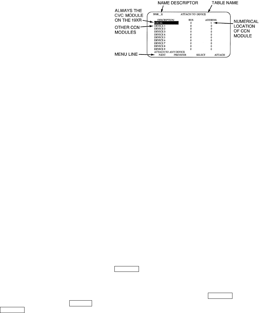
Figure 24 shows the ATTACH TO NETWORK DEVICE
screen. The LOCAL parameter is always the CVC/ICVC mod-
ule address of the chiller on which it is mounted. Whenever the
controller identification of the CVC/ICVC changes, the change
is reflected automatically in the BUS and ADDRESS columns
for the local device. See Fig. 18. Default address for local de-
vice is BUS 0 ADDRESS 1.
When the ATTACH TO NETWORK DEVICE screen is ac-
cessed, information can not be read from the CVC/ICVC on
any device until one of the devices listed on that screen is at-
tached. The CVC/ICVC erases information about the module
to which it was attached to make room for information on an-
other device. Therefore, a CCN module must be attached when
this screen is entered.
To attach any CCN device, highlight it using the
softkey and press the softkey. The message “UP-
LOADING TABLES, PLEASE WAIT” displays. The CVC/
ICVC then uploads the highlighted device or module. If the
module address cannot be found, the message “COMMUNI-
CATION FAILURE” appears. The CVC/ICVC then reverts
back to the ATTACH TO DEVICE screen. Try another device
or check the address of the device that would not attach. The
upload process time for each CCN module is different. In gen-
eral, the uploading process takes 1 to 2 minutes. Before leaving
the ATTACH TO NETWORK DEVICE screen, select the lo-
cal device. Otherwise, the CVC/ICVC will be unable to display
information on the local chiller.
ATTACHING TO OTHER CCN MODULES — If the chill-
er CVC/ICVC has been connected to a CCN Network or other
PIC controlled chillers through CCN wiring, the CVC/ICVC
can be used to view or change parameters on the other control-
lers. Other PIC II chillers can be viewed and set points changed
(if the other unit is in CCN control), if desired, from this partic-
ular CVC/ICVC module.
If the module number is not valid, the “COMMUNICA-
TION FAILURE” message will show and a new address num-
ber must be entered or the wiring checked. If the module is
communicating properly, the “UPLOAD IN PROGRESS”
message will flash and the new module can now be viewed.
Whenever there is a question regarding which module on
the CVC/ICVC is currently being shown, check the device
name descriptor on the upper left hand corner of the CVC/
ICVC screen. See Fig. 24.
When the CCN device has been viewed, the ATTACH TO
NETWORK DEVICE table should be used to attach to the PIC
that is on the chiller. Move to the ATTACH TO NETWORK
DEVICE table (LOCAL should be highlighted) and press the
softkey to upload the LOCAL device. The CVC/
ICVC for the 19XR will be uploaded and default screen will
display.
NOTE: The CVC/ICVC will not automatically reattach to the
local module on the chiller. Press the softkey to
attach to the LOCAL device and view the chiller operation.
SELECT
ATTA CH
ATTA CH
ATTA CH
Fig. 24 — Example of Attach to Network
Device Screen


