


74
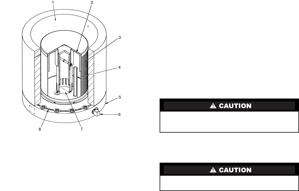
Inspect Refrigerant Float System —
Perform this
inspection every 5 years or when the condenser is opened for
service.
1. Transfer the refrigerant into the cooler vessel or into a
pumpout storage tank.
2. Remove the float access cover.
3. Clean the chamber and valve assembly thoroughly. Be
sure the valve moves freely. Ensure that all openings are
free of obstructions.
4. Examine the cover gasket and replace if necessary.
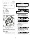
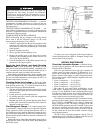
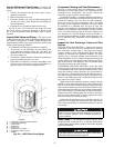
See Fig. 38 for a view of the float valve design. For linear
float valve designs, inspect the orientation of the float slide
pin. It must be pointed toward the bubbler tube for proper
operation.
Inspect Relief Valves and Piping —
The relief valves
on this chiller protect the system against the potentially danger-
ous effects of overpressure. To ensure against damage to the
equipment and possible injury to personnel, these devices must
be kept in peak operating condition.
As a minimum, the following maintenance is required.
1. At least once a year, disconnect the vent piping at the
valve outlet and carefully inspect the valve body and
mechanism for any evidence of internal corrosion or rust,
dirt, scale, leakage, etc.
2. If corrosion or foreign material is found, do not attempt to
repair or recondition. Replace the valve.
3. If the chiller is installed in a corrosive atmosphere or the
relief valves are vented into a corrosive atmosphere, in-
spect the relief valves at more frequent intervals.
Compressor Bearing and Gear Maintenance —
The key to good bearing and gear maintenance is proper
lubrication. Use the proper grade of oil, maintained at rec-
ommended level, temperature, and pressure. Inspect the
lubrication system regularly and thoroughly.
To inspect the bearings, a complete compressor teardown is
required. Only a trained service technician should remove and
examine the bearings. The cover plate on older compressor
bases was used for factory-test purposes and is not usable
for bearing or gear inspection. The bearings and gears should
be examined on a scheduled basis for signs of wear. The
frequency of examination is determined by the hours of chiller
operation, load conditions during operation, and the condition
of the oil and the lubrication system. Excessive bearing wear
can sometimes be detected through increased vibration or
increased bearing temperature. If either symptom appears, con-
tact an experienced and responsible service organization for
assistance.
Inspect the Heat Exchanger Tubes and Flow
Devices
COOLER AND FLOW DEVICES — Inspect and clean the
cooler tubes at the end of the first operating season. Because
these tubes have internal ridges, a rotary-type tube cleaning
system is needed to fully clean the tubes. Inspect the tubes’
condition to determine the scheduled frequency for future
cleaning and to determine whether water treatment in the
chilled water/brine circuit is adequate. Inspect the entering and
leaving chilled water temperature sensors and flow devices for
signs of corrosion or scale. Replace a sensor or Schrader fitting
if corroded or remove any scale if found.
CONDENSER AND FLOW DEVICES — Since this water
circuit is usually an open-type system, the tubes may be subject
to contamination and scale. Clean the condenser tubes with a
rotary tube cleaning system at least once per year and more of-
ten if the water is contaminated. Inspect the entering and leav-
ing condenser water sensors and flow devices for signs of cor-
rosion or scale. Replace the sensor or Schrader fitting if corrod-
ed or remove any scale if found.
Higher than normal condenser pressures, together with the
inability to reach full refrigeration load, usually indicate dirty
tubes or air in the chiller. If the refrigeration log indicates a rise
above normal condenser pressures, check the condenser refrig-
erant temperature against the leaving condenser water tempera-
ture. If this reading is more than what the design difference is
supposed to be, the condenser tubes may be dirty or water flow
may be incorrect. Because HFC-134a is a high-pressure refrig-
erant, air usually does not enter the chiller.
During the tube cleaning process, use brushes specially de-
signed to avoid scraping and scratching the tube wall. Contact
your Carrier representative to obtain these brushes. Do not use
wire brushes.
Water Leaks —
The refrigerant moisture indicator on the
refrigerant motor cooling line (Fig. 2) indicates whether there
is water leakage during chiller operation. Water leaks should be
repaired immediately.
Hard scale may require chemical treatment for its preven-
tion or removal. Consult a water treatment specialist for
proper treatment.
The chiller must be dehydrated after repair of water leaks.
See Chiller Dehydration section, page 53.
LEGEND
Fig. 38 — 19XR Float Valve Design
1 — Refrigerant Inlet from FLASC Chamber
2 — Linear Float Assembly
3 — Float Screen
4 — Bubble Line
5 — Float Cover
6 — Bubble Line Connection
7 — Refrigerant Outlet to Cooler
8 — Gasket