


37
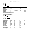
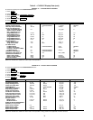
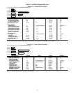
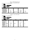
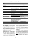
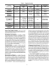
Table 4 — Capacity Overrides
Alarm (Trip) Output Contacts —
One set of alarm
contacts is provided in the starter. The contact ratings are pro-
vided in the certified drawings. The contacts are located on ter-
minal strip J9, terminals 15 and 16.
Refrigerant Leak Detector —
An input is available
on the CCM module [terminal J5-5 (–) and J5-6 (+)] for a
refrigerant leak detector. Enabling REFRIGERANT LEAK
OPTION (OPTIONS screen) will allow the PIC II controls to
go into an alarm state at a user configured level (REFRIGER-
ANT LEAK ALARM mA). The input is configured for 4 to
20 mA by setting the DIP switch 1 on SW2 at the ON position,
or configured for 1 to 5 vdc by setting switch 1 at the OFF posi-
tion. The output of the refrigerant leak detector is displayed as
REFRIGERANT LEAK SENSOR on the MAINSTAT screen.
For a 1 to 5 vdc input, 1 vdc input represents 4 mA displayed
and 5 vdc input represents 20 mA displayed.
Kilowatt Output —
An output is available on the CCM
module [Terminal J8-1 (+) and J8-2 (–)] to represent the power
consumption of the chiller. The 4 to 20 mA signal generated by
the CCM module can be wired to the building automation or
energy management system to monitor the chiller’s energy
consumption. A 4 mA signal represents the chiller in an off
state and a 20 mA signal represents the chiller operating at its
rated peak kilowatt consumption. The rated peak kilowatt con-
sumption is configured by the user in the RAMP_DEM display
screen by the setting the MOTOR RATED KILOWATTS from
the job data sheet.
Remote Reset of Alarms —
A standard feature of the
PIC II controls is the ability to reset a chiller in a shutdown
alarm state from a remote location. If the condition which
caused the alarm has cleared the chiller can be placed back into
a normal CCN operating mode when the REMOTE RESET
OPTION (CVC_PSWD/ICVC_PSWD menu) is set to EN-
ABLE. A variety of Carrier Comfort Network software sys-
tems including ComfortVIEW™ or Network Service Tool™
can access the PIC II controls and reset the displayed alarm.
Third party software from building automation systems (BAS)
or energy management systems (EMS) can also access the
PIC II controls through a Carrier DataLINK™ module and re-
set the fault displayed. Both methods would access the
CVC_PSWD/ICVC_PSWD screen and force the RESET
ALARM? point to YES to reset the fault condition. If the PIC II
controls have determined that is safe to start the chiller the
CCN MODE? point (CVC_PSWD/ICVC_PSWD screen) can
be forced to YES to place the chiller back into normal CCN op-
erating mode. The only exceptions are the following alarms
that cannot be reset from a remote location: STATE #100, 205,
217-220, 223, 233, 234, 247, and 250. To view alarm codes, re-
fer to Troubleshooting Guide, Checking Display Messages,
page 76. After the alarm has been reset the PIC II control will
increment the Starts in 12 Hours counter by one upon restart. If
the limit of 8 starts in a 12-hour period occurs the alarm will be
required to be reset at the chiller control panel (CVC/ICVC).
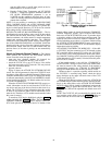
Condenser Pump Control —
The chiller will moni-
tor the condenser pressure (CONDENSER PRESSURE) and
may turn on the condenser pump if the condenser pressure be-
comes too high while the compressor is shut down. The con-
denser pressure override (COND PRESS OVERRIDE) parame-
ter is used to determine this pressure point. COND PRESS
OVERRIDE is found in the SETUP1 display screen, which is
accessed from the EQUIPMENT SERVICE table. The default
value is 125 psig (862 kPa).
If the CONDENSER PRESSURE is greater than or equal to
the COND PRESS OVERRIDE, and the entering condenser
water temperature (ENTERING CONDENSER WATER) is less
than 115 F (46 C), the condenser pump will energize to try to
decrease the pressure. The pump will turn off when the con-
denser pressure is 3.5 psi (24.1 kPa) less than the pressure over-
ride or when the condenser refrigerant temperature (CON-
DENSER REFRIG TEMP) is within 3° F (1.7° C) of the enter-
ing condenser water temperature (ENTERING CONDENSER
WATER).
OVERRIDE
CAPACITY CONTROL
FIRST STAGE SET POINT
SECOND STAGE SET
POINT
OVERRIDE
TERMINATION
View/Modify
on CVC/ICVC
Screen
Default
Value
Configurable
Range
Value Value
HIGH CONDENSER
PRESSURE
SETUP1
125 psig
(862 kPa)
90 to 165 psig
(620 to 1138 kPa)
>Override
Set Point
+2.4 psid (16.5 kPad)
<Override
Set Point
HIGH MOTOR
TEMPERATURE
SETUP1
>200 F
(93.3 C)
150 to 200 F
(66 to 93 C)
>Override
Set Point
+10° F (6° C)
<Override
Set Point
LOW REFRIGERANT
TEMPERATURE
(Refrigerant
Override Delta
Temperature)
SETUP1 3° F (1.6° C)
2° to 5° F
(1° to 3° C)
≤Trippoint
+ Override
∆T –1° F (0.56° C)
>Trippoint
+ Override
∆T+2° F (1.2° C)
HIGH COMPRESSOR
LIFT
(Surge Prevention)
OPTIONS
Min: T1 — 1.5° F
(0.8° C)
P1 — 50 psid
(345 kPad)
Max: T2 — 10° F
(5.6° C)
P2 — 85 psid
(586 kPad)
0.5° to 20° F
(0.3° to 8.3° C)
30 to 170 psid
(207 to 1172 kPad)
0.5° to 20° F
(0.3° to 8.3° C)
50 to 170 psid
(348 to 1172 kPad)
None
Within Lift Limits
Plus Surge/HGBP
Deadband Setting
MANUAL GUIDE VANE
TARGET
CAPACITY Automatic 0 to 100% None
Release of
Manual Control
MOTOR LOAD —
ACTIVE DEMAND LIMIT
MAINSTAT 100% 40 to 100%
≥5% of
Set Point
2% Lower
Than Set Point
LOW DISCHARGE
SUPERHEAT
OVERRIDE
Calculated Minimum
Superheat for
Conditions
None
2° F (1.1° C)
Below Calculated
Minimum Superheat
1° F (0.56° C)
Above Calculated
Minimum Superheat