


13
The PIC II can interface with the Carrier Comfort Network
(CCN) if desired. It can communicate with other PIC I or PIC
II equipped chillers and other CCN devices.
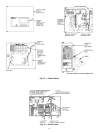
The PIC II consists of 3 modules housed inside 3 major
components. The component names and corresponding control
voltages are listed below (also see Table 1):
• control panel
— all extra low-voltage wiring (24 v or less)
• power panel
— 230 or 115 v control voltage (per job requirement)
— up to 600 v for oil pump power
• starter cabinet
— chiller power wiring (per job requirement)
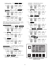
Table 1 — Major PIC II Components and
Panel Locations*
*See Fig. 8-13.
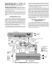
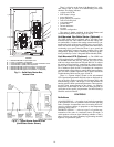
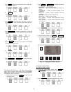
CHILLER VISUAL CONTROLLER (CVC) — The CVC is
the “brain” of the PIC II. This module contains all the operating
software needed to control the chiller. The CVC is mounted to
the control panel (Fig. 12) and is the input center for all local
chiller set points, schedules, configurable functions, and op-
tions. The CVC has a stop button, an alarm light, four buttons
for logic inputs, and a backlight display. The backlight will au-
tomatically turn off after 15 minutes of non-use. The functions
of the four buttons or “softkeys” are menu driven and are
shown on the display directly above the softkeys.
The viewing angle of the CVC can be adjusted for optimum
viewing. Remove the 2 bolts connecting the control panel to
the brackets attached to the cooler. Place them in one of the
holes to pivot the control panel forward to backward to change
the viewing angle. See Fig. 12. To change the contrast of the
display, access the adjustment on the back of the CVC. See
Fig. 12.
INTERNATIONAL CHILLER VISUAL CONTROLLER
(ICVC) — Incorporates all of the functions and operating soft-
ware of the CVC with the added feature of 4 factory pro-
grammed languages:
English (default)
Chinese
Japanese
Korean
NOTE: Pressing any one of the four softkey buttons will acti-
vate the backlight display without implementing a softkey
function.
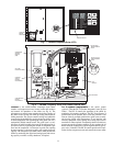
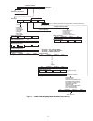
INTEGRATED STARTER MODULE (ISM) — This mod-
ule is located in the starter cabinet. This module initiates com-
mands from the CVC/ICVC for starter functions such as start-
ing and stopping the compressor, condenser, chilled water
pumps, tower fan, spare alarm contacts, and the shunt trip. The
ISM monitors starter inputs such as line voltage, motor current,
ground fault, remote start contact, spare safety, condenser high
pressure, oil pump interlock, starter 1M, and run contacts. The
ISM contains logic capable of safety shutdown. It shuts down
the chiller if communications with the CVC/ICVC are lost.
The ISM can also act as the interface for PIC II to the VFD
controller.
CHILLER CONTROL MODULE (CCM) — This module is
located in the control panel. The CCM provides the input and
outputs necessary to control the chiller. This module monitors
refrigerant pressure, entering and leaving water temperatures,
and outputs control for the guide vane actuator, oil heaters, and
oil pump. The CCM is the connection point for optional de-
mand limit, chilled water reset, remote temperature reset, re-
frigerant leak sensor and motor kilowatt output.
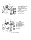
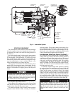
OIL HEATER CONTACTOR (1C) — This contactor is lo-
cated in the power panel (Fig. 13) and operates the heater at
either 115 or 230 v. It is controlled by the PIC II to maintain oil
temperature during chiller shutdown. The XR4 with split ring
diffuser has a line voltage oil heater. Refer to the control panel
wiring schematic.
OIL PUMP CONTACTOR (2C) — This contactor is located
in the power panel. It operates all 200 to 575-v oil pumps.
The PIC II energizes the contactor to turn on the oil pump as
necessary.
HOT GAS BYPASS CONTACTOR RELAY (3C)
(Optional) — This relay, located in the power panel, controls
the opening of the hot gas bypass valve. The PIC II energizes
the relay during low load, high lift conditions.
CONTROL TRANSFORMERS (T1, T2) — These transform-
ers convert incoming control voltage to 24 vac power for the
3 power panel contactor relays, CCM, and CVC/ICVC.
OPTIONAL TRANSFORMER (T3) — This transformer pro-
vides control power to Dataport™/DataLINK™ modules.
PIC II COMPONENT PANEL LOCATION
Chiller Visual Controller (CVC/ICVC) and
Display
Control Panel
Integrated Starter Module (ISM) Starter Cabinet
Chiller Control Module (CCM) Control Panel
Oil Heater Contactor (1C) Power Panel
Oil Pump Contactor (2C) Power Panel
Hot Gas Bypass Relay (3C) (Optional) Power Panel
Control Transformers (T1, T2) Power Panel
Temperature Sensors See Fig. 9.
Pressure Transducers See Fig. 9.
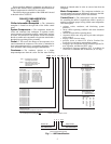
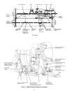
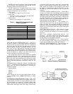
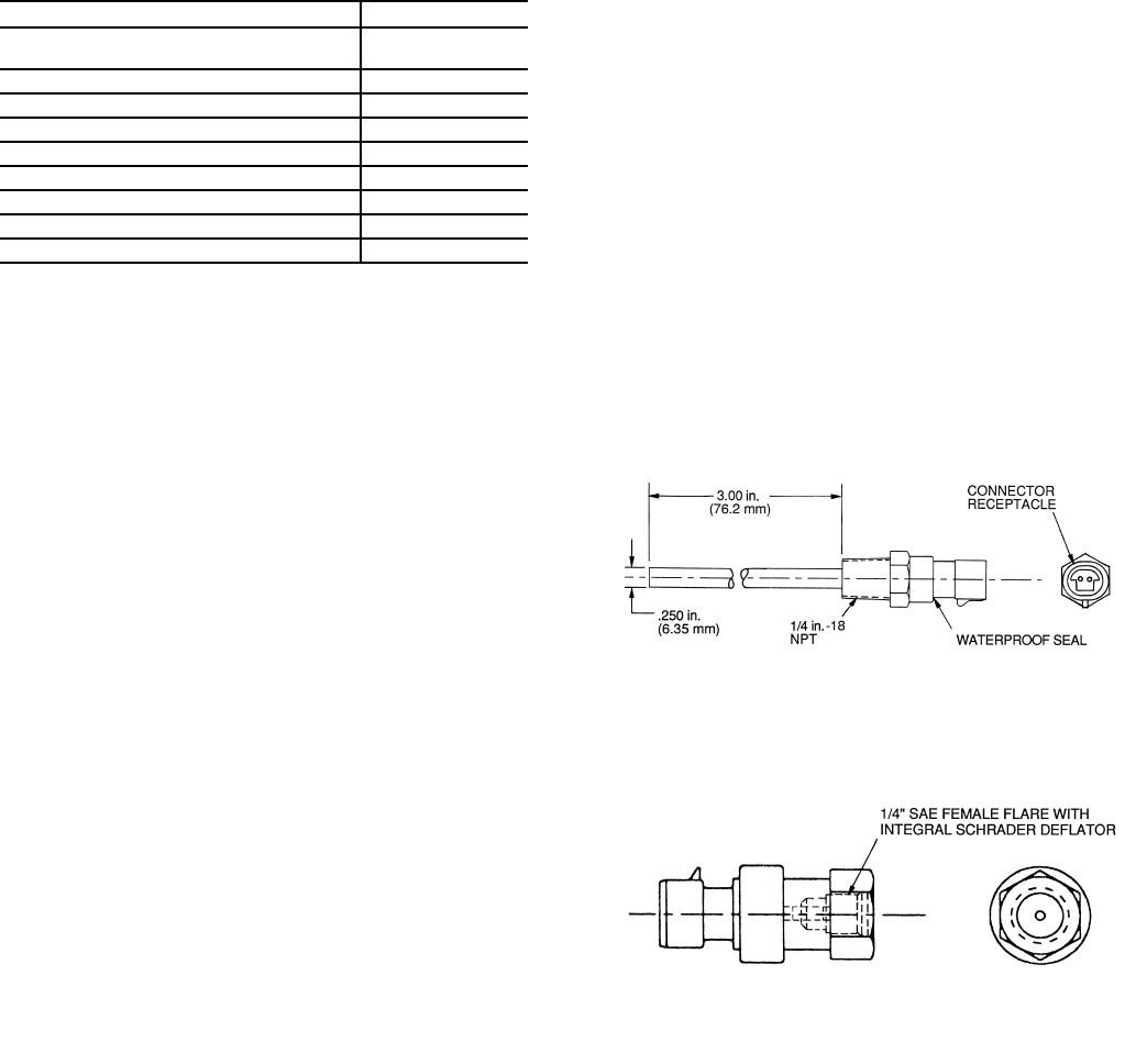
Fig. 10 — Control Sensors (Temperature)
Fig. 11 — Control Sensors
(Pressure Transducers, Typical)