


62
Owner-Modified CCN Tables
— The following EQUIP-
MENT CONFIGURATION screens are described for refer-
ence only.
OCCDEFCS — The OCCDEFCS screen contains the Local
and CCN time schedules, which can be modified here or on the
SCHEDULE screen as described previously.
HOLIDAYS — From the HOLIDAYS screen, the days of the
year that holidays are in effect can be configured. See the holi-
day paragraphs in the Controls section for more details.
BRODEF — The BRODEF screen defines the start and end of
daylight savings time. Enter the dates for the start and end of
daylight savings if required for your location. BRODEF also
activates the Broadcast function which enables the holiday
periods that are defined on the CVC/ICVC to take effect.
Other Tables — The CONSUME, NET_OPT, and RUN-
TIME screens contain parameters used with a CCN system.
See the applicable CCN manual for more information on these
screens. These tables can only be defined from a CCN Build-
ing Supervisor.
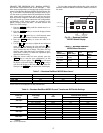
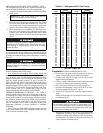
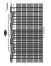
Perform a Control Test —
Check the safety controls
status by performing an automated control test. Access the
CONTROL TEST table and select a test to be performed func-
tion (Table 9).
The Automated Control Test checks all outputs and inputs
for function. In order to successfully proceed with the controls
test, the compressor should be off, no alarms showing, and volt-
age should be within ±10% of rating plate value. The compres-
sor can be put in OFF mode by pressing the STOP push-button
on the CVC/ICVC. Each test asks the operator to confirm the
operation is occurring and whether or not to continue. If an er-
ror occurs, the operator can try to address the problem as the
test is being done or note the problem and proceed to the next
test.
NOTE: Enter guide vane calibration to calibrate guide
input on CCM (Plug J4 upper terminal 9 and 10).
NOTE: If during the control test the guide vanes do not open,
verify the low pressure alarm is not active. (An active low
pressure alarm causes the guide vanes to close.)
NOTE: The oil pump test will not energize the oil pump if
cooler pressure is below –5 psig (–35 kPa).
When the control test is finished or the softkey is
pressed, the test stops, and the CONTROL TEST menu dis-
plays. If a specific automated test procedure is not completed,
access the particular control test to test the function when ready.
The CONTROL TEST menu is described in the table below.
*Diffuser tests function only on size 4 and 5 compressor with diffuser control
enabled.
NOTE: During any of the tests, an out-of-range reading will have an asterisk
(*) next to the reading and a message will be displayed if you have diffuser
control enabled.
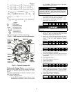
COOLER CONDENSER PRESSURE TRANSDUCER
AND WATERSIDE FLOW DEVICE CALIBRATION
(Optional with ICVC inputs available) — Calibration can be
checked by comparing the pressure readings from the
transducer to an accurate refrigeration gage reading. These
readings can be viewed or calibrated from the HEAT_EX
screen on the CVC/ICVC. The transducer can be checked and
calibrated at 2 pressure points. These calibration points are
0 psig (0 kPa) and between 25 and 250 psig (173 and
1724 kPa). To calibrate these transducers:
1. Shut down the compressor, cooler, and condenser pumps.
NOTE: There should be no flow through the heat
exchangers.
2. Disconnect the transducer in question from its Schrader
fitting for cooler or condenser transducer calibration. For
oil pressure or flow device calibration keep transducer in
place.
NOTE: If the cooler or condenser vessels are at 0 psig
(0 kPa) or are open to atmospheric pressure, the transduc-
ers can be calibrated for zero without removing the trans-
ducer from the vessel.
3. Access the HEAT_EX screen and view the particular
transducer reading (the EVAPORATOR PRESSURE or
CONDENSER PRESSURE parameter on the HEAT_EX
screen). To calibrate oil pressure or waterside flow de-
vice, view the particular reading (CHILLED WATER
DELTA P and CONDENSER WATER DELTA P on the
HEAT_EX screen and OIL PUMP DELTA P on the
COMPRESS screen). It should read 0 psi (0 kPa). If the
reading is not 0 psi (0 kPa), but within ±5 psi (35 kPa),
the value may be set to zero by pressing the
softkey while the appropriate transducer parameter is
highlighted on the CVC/ICVC screen. Then press the
softkey. The value will now go to zero. No high
end calibration is necessary for OIL PUMP DELTA P or
flow devices.
If the transducer value is not within the calibration range,
the transducer returns to the original reading. If the pres-
sure is within the allowed range (noted above), check the
voltage ratio of the transducer. To obtain the voltage ratio,
divide the voltage (dc) input from the transducer by the
supply voltage signal (displayed in CONTROL TEST
menu in the CCM PRESSURE TRANSDUCERS
screen) or measure across the positive (+ red) and nega-
tive (– black) leads of the transducer. For example, the
condenser transducer voltage input is measured at CCM
terminals J2-4 and J2-5. The voltage ratio must be be-
tween 0.80 and 0.11 for the software to allow calibration.
Rotate the waterside flow pressure device from the inlet
nozzle to the outlet nozzle and repeat this step. If rotating
the waterside flow device does not allow calibration then
pressurize the transducer until the ratio is within range.
Then attempt calibration again.
4. A high pressure point can also be calibrated between 25
and 250 psig (172.4 and 1723.7 kPa) by attaching a regu-
lated 250 psig (1724 kPa) pressure (usually from a nitro-
gen cylinder). The high pressure point can be calibrated
by accessing the appropriate transducer parameter on the
HEAT_EX screen, highlighting the parameter, pressing
the softkey, and then using the
or softkeys to adjust the value to the exact
pressure on the refrigerant gage. Press the soft-
key to finish the calibration. Pressures at high altitude lo-
cations must be compensated for, so the chiller tempera-
ture/pressure relationship is correct.
The PIC II does not allow calibration if the transducer is too
far out of calibration. In this case, a new transducer must be
installed and recalibrated.
CCM Temperature Thermistors Check of all thermistors.
CCM Pressure Transducers Check of all transducers.
Pump
Checks operation of pump outputs;
pumps are activated. Also tests associ-
ated inputs such as flow or pressure.
Discrete outputs
Activation of all on/off outputs individu-
ally.
Guide Vane Check of the guide vane operation.
Diffuser Actuator* Check of the diffuser actuator.
Pumpdown/Lockout
Pumpdown prevents the low refrigerant
alarm during evacuation so refrigerant
can be removed form the unit. Also locks
the compressor off and starts the water
pumps.
Terminate Lockout
To charge refrigerant and enable the
chiller to run after pumpdown lockout.
Guide Vane Calibration Calibrates guide vane input on CCM.
EXIT
SELECT
ENTER
SELECT INCREASE
DECREASE
ENTER