


76
TROUBLESHOOTING GUIDE
Overview —
The PIC II has many features to help the op-
erator and technician troubleshoot a 19XR chiller.
• The CVC/ICVC shows the chiller’s actual operating con-
ditions and can be viewed while the unit is running.
• The CVC/ICVC default screen freezes when an alarm
occurs. The freeze enables the operator to view the
chiller conditions at the time of alarm. The STATUS
screens continue to show current information. Once all
alarms have been cleared (by correcting the problems
and pressing the softkey), the CVC/ICVC
default screen returns to normal operation.
• The CONTROL ALGORITHM STATUS screens (which
include the CAPACITY, OVERRIDE, LL_MAINT,
ISM_HIST, LOADSHED, WSMDEFME, and
OCCDEFCM screens) display information that helps to
diagnose problems with chilled water temperature
control, chilled water temperature control overrides, hot
gas bypass, surge algorithm status, and time schedule
operation.
• The control test feature facilitates the proper operation
and test of temperature sensors, pressure transducers, the
guide vane actuator, oil pump, water pumps, tower con-
trol, and other on/off outputs while the compressor is
stopped. It also has the ability to lock off the compressor
and turn on water pumps for pumpout operation. The
CVC/ICVC shows the temperatures and pressures
required during these operations.
• From other SERVICE tables, the operator/technician can
access configured items, such as chilled water resets,
override set points, etc.
• If an operating fault is detected, an alarm message is gen-
erated and displayed on the CVC/ICVC default screen.
A more detailed message — along with a diagnostic
message — is also stored into the ALARM HISTORY
table.
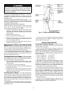
Checking Display Messages —
The first area to
check when troubleshooting the 19XR is the CVC/ICVC dis-
play. If the alarm light is flashing, check the primary and sec-
ondary message lines on the CVC/ICVC default screen
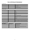
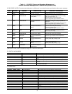
(Fig. 14). These messages will indicate where the fault is oc-
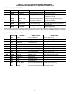
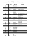
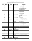
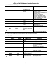
curring. These messages contain the alarm message with a
specified code. This code or state appears with each alarm and
alert message. The ALARM HISTORY table on the CVC/
ICVC SERVICE menu also contains an alarm message to fur-
ther expand on the alarm. For a complete list of possible alarm
messages, see Table 11. If the alarm light starts to flash while
accessing a menu screen, press the softkey to return to
the default screen to read the alarm message. The STATUS
screen can also be accessed to determine where an alarm exists.
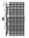
Checking Temperature Sensors —
All temperature
sensors are thermistor-type sensors. This means that the resis-
tance of the sensor varies with temperature. All sensors have
the same resistance characteristics. If the controls are on, deter-
mine sensor temperature by measuring voltage drop; if the con-
trols are powered off, determine sensor temperature by measur-
ing resistance. Compare the readings to the values listed in
Table 12A or 12B.
RESISTANCE CHECK — Turn off the control power and,
from the module, disconnect the terminal plug of the sensor in
question. With a digital ohmmeter, measure sensor resistance
between receptacles as designated by the wiring diagram. The
resistance and corresponding temperature are listed in
Table 12A or 12B. Check the resistance of both wires to
ground. This resistance should be infinite.
VOLTAGE DROP — The voltage drop across any energized
sensor can be measured with a digital voltmeter while the con-
trol is energized. Table 12A or 12B lists the relationship be-
tween temperature and sensor voltage drop (volts dc measured
across the energized sensor). Exercise care when measuring
voltage to prevent damage to the sensor leads, connector plugs,
and modules. Sensors should also be checked at the sensor
plugs. Check the sensor wire at the sensor for 5 vdc if the con-
trol is powered on.
CHECK SENSOR ACCURACY — Place the sensor in a
medium of known temperature and compare that temperature
to the measured reading. The thermometer used to determine
the temperature of the medium should be of laboratory quality
with 0.5° F (.25° C) graduations. The sensor in question should
be accurate to within 2° F (1.2° C).
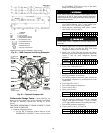
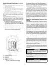
See Fig. 9 for sensor locations. The sensors are immersed
directly in the refrigerant or water circuits. The wiring at each
sensor is easily disconnected by unlatching the connector.
These connectors allow only one-way connection to the sensor.
When installing a new sensor, apply a pipe sealant or thread
sealant to the sensor threads.
DUAL TEMPERATURE SENSORS — For servicing con-
venience, there are 2 sensors each on the bearing and motor
temperature sensors. If one of the sensors is damaged, the other
can be used by simply moving a wire. The number 2 terminal
in the sensor terminal box is the common line. To use the sec-
ond sensor, move the wire from the number 1 position to the
number 3 position.
Checking Pressure Transducers
UNITS EQUIPPED WITH CVC — There are 8 pressure
transducers on 19XR chillers. They determine cooler, condens-
er, oil pressure, and cooler and condenser flow. The cooler and
condenser transducers are also used by the PIC II to determine
the refrigerant temperatures. The oil supply pressure transducer
value and the oil transmission sump pressure transducer value
difference is calculated by the CCM. The CVC module then
displays the differential pressure. In effect, the CVC reads only
one input for oil pressure for a total of 5 pressure inputs: cooler
pressure, condenser pressure, oil differential pressure, cooler
waterside differential pressure, and condenser waterside differ-
ential pressure. See the Check Pressure Transducers section
(page 75) under Scheduled Maintenance.
UNITS EQUIPPED WITH ICVC — There are 6 factory-
installed pressure transducers, with inputs available for both
cooler and The ICVC software will display a default reading of
26 psi during start-up and operation. An additional transducer,
factory installed in the bottom of the cooler barrel, will read as
EVAPORATOR SACTURATION TEMP on the HEAT_EX
DISPLAY screen. This provides additional protection against a
loss of water flow condition.
These pressure transducers can be calibrated if necessary. It
is not usually necessary to calibrate at initial start-up.
However, at high altitude locations, it is necessary to calibrate
the transducers to ensure the proper refrigerant temperature/
pressure relationship. Each transducer is supplied with 5 vdc
power from the CCM. If the power supply fails, a transducer
voltage reference alarm occurs. If the transducer reading is
suspected of being faulty, check the supply voltage. It should
be 5 vdc ±.5 v displayed in CONTROL TEST under CCM
Pressure Transducers. If the supply voltage is correct, the trans-
ducer should be recalibrated or replaced.
RESET
EXIT
Relieve all refrigerant pressure or drain the water before
replacing the temperature sensors.