


75
Water Treatment —
Untreated or improperly treated wa-
ter may result in corrosion, scaling, erosion, or algae. The ser-
vices of a qualified water treatment specialist should be ob-
tained to develop and monitor a treatment program.
Inspect the Starting Equipment —
Before working
on any starter, shut off the chiller, open and tag all disconnects
supplying power to the starter.
Inspect starter contact surfaces for wear or pitting on
mechanical-type starters. Do not sandpaper or file silverplated
contacts. Follow the starter manufacturer’s instructions for
contact replacement, lubrication, spare parts ordering, and oth-
er maintenance requirements.
Periodically vacuum or blow off accumulated debris on the
internal parts with a high-velocity, low-pressure blower.
Power connections on newly installed starters may relax
and loosen after a month of operation. Turn power off and re-
tighten. Recheck annually thereafter.
Check Pressure Transducers —
Once a year, the
pressure transducers should be checked against a pressure gage
reading. Check all eight transducers: the 2 oil differential pres-
sure transducers, the condenser pressure transducer, the cooler
pressure transducer, and the waterside pressure transducers
(consisting of 4 flow devices: 2 cooler, 2 condenser).
Note the evaporator and condenser pressure readings on the
HEAT_EX screen on the CVC/ICVC (EVAPORATOR PRES-
SURE and CONDENSER PRESSURE). Attach an accurate set
of refrigeration gages to the cooler and condenser Schrader fit-
tings. Compare the two readings. If there is a difference in
readings, the transducer can be calibrated as described in the
Troubleshooting Guide section. Oil differential pressure (OIL
PUMP DELTA P on the COMPRESS screen) should be zero
whenever the compressor is off.
Optional Pumpout System Maintenance —
For
pumpout unit compressor maintenance details, refer to the
06D, 07D Installation, Start-Up, and Service Instructions.
OPTIONAL PUMPOUT COMPRESSOR OIL CHARGE —
Use oil conforming to Carrier specifications for reciprocat-
ing compressor usage. Oil requirements are as follows:
ISO Viscosity . . . . . . . . . . . . . . . . . . . . . . . . . . . . . . . . . . . . . . 68
Carrier Part Number . . . . . . . . . . . . . . . . . . . . . . . . PP23BZ103
The total oil charge, 4.5 pints (2.6 L), consists of 3.5 pints
(2.0 L) for the compressor and one additional pint (0.6 L) for
the oil separator.
Oil should be visible in one of the compressor sight glasses
during both operation and at shutdown. Always check the oil
level before operating the compressor. Before adding or chang-
ing oil, relieve the refrigerant pressure as follows:
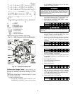
1. Attach a pressure gage to the gage port of either compres-
sor service valve (Fig. 36).
2. Close the suction service valve and open the discharge
line to the storage tank or the chiller.
3. Operate the compressor until the crankcase pressure
drops to 2 psig (13 kPa).
4. Stop the compressor and isolate the system by closing the
discharge service valve.
5. Slowly remove the oil return line connection (Fig. 36).
Add oil as required.
6. Replace the connection and reopen the compressor ser-
vice valves.
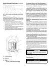
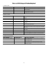
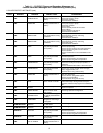
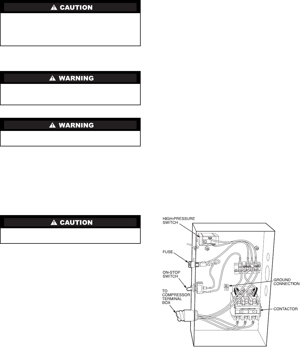
OPTIONAL PUMPOUT SAFETY CONTROL SETTINGS
(Fig. 39) — The optional pumpout system high-pressure
switch opens at 161 psig (1110 kPa) and closes at 130 psig
(896 kPa). Check the switch setting by operating the pumpout
compressor and slowly throttling the pumpout condenser
water.
Ordering Replacement Chiller Parts —
When
ordering Carrier specified parts, the following information
must accompany an order:
• chiller model number and serial number
• name, quantity, and part number of the part required
• delivery address and method of shipment.
Water must be within design flow limits, clean, and treated
to ensure proper chiller performance and reduce the poten-
tial of tube damage due to corrosion, scaling, erosion, and
algae. Carrier assumes no responsibility for chiller damage
resulting from untreated or improperly treated water.
The disconnect on the starter front panel does not deener-
gize all internal circuits. Open all internal and remote dis-
connects before servicing the starter.
Never open isolating knife switches while equipment is
operating. Electrical arcing can cause serious injury.
Loose power connections can cause voltage spikes, over-
heating, malfunctioning, or failures.
Fig. 39 — Optional Pumpout System Controls