


4
CONTENTS (cont)
Page
Inspect Relief Valves and Piping. . . . . . . . . . . . . . . . . 74
Compressor Bearing and Gear
Maintenance . . . . . . . . . . . . . . . . . . . . . . . . . . . . . . . . . . 74
Inspect the Heat Exchanger Tubes
and Flow Devices . . . . . . . . . . . . . . . . . . . . . . . . . . . . . 74
• COOLER AND FLOW DEVICES
• CONDENSER AND FLOW DEVICES
Water Leaks . . . . . . . . . . . . . . . . . . . . . . . . . . . . . . . . . . . . . 74
Water Treatment . . . . . . . . . . . . . . . . . . . . . . . . . . . . . . . . . 75
Inspect the Starting Equipment. . . . . . . . . . . . . . . . . . 75
Check Pressure Transducers . . . . . . . . . . . . . . . . . . . . 75
Optional Pumpout System Maintenance. . . . . . . . . 75
• OPTIONAL PUMPOUT COMPRESSOR OIL
CHARGE
• OPTIONAL PUMPOUT SAFETY CONTROL
SETTINGS
Ordering Replacement Chiller Parts . . . . . . . . . . . . . 75
TROUBLESHOOTING GUIDE . . . . . . . . . . . . . . . . 76-122
Overview . . . . . . . . . . . . . . . . . . . . . . . . . . . . . . . . . . . . . . . . 76
Checking Display Messages. . . . . . . . . . . . . . . . . . . . . 76
Checking Temperature Sensors . . . . . . . . . . . . . . . . . 76
• RESISTANCE CHECK
• VOLTAGE DROP
• CHECK SENSOR ACCURACY
• DUAL TEMPERATURE SENSORS
Checking Pressure Transducers. . . . . . . . . . . . . . . . . 76
• UNITS EQUIPPED WITH CVC
• UNITS EQUIPPED WITH ICVC
• TRANSDUCER REPLACEMENT
Control Algorithms Checkout Procedure . . . . . . . . 77
Control Test . . . . . . . . . . . . . . . . . . . . . . . . . . . . . . . . . . . . . 77
Control Modules. . . . . . . . . . . . . . . . . . . . . . . . . . . . . . . . . 87
• RED LED (Labeled as STAT)
• GREEN LED (Labeled as COM)
Notes on Module Operation . . . . . . . . . . . . . . . . . . . . . 87
Chiller Control Module (CCM) . . . . . . . . . . . . . . . . . . . 88
• INPUTS
• OUTPUTS
Integrated Starter Module . . . . . . . . . . . . . . . . . . . . . . . 88
• INPUTS
• OUTPUTS
Replacing Defective Processor Modules . . . . . . . . 88
• INSTALLATION
Solid-State Starters. . . . . . . . . . . . . . . . . . . . . . . . . . . . . . 88
• TESTING SILICON CONTROL RECTIFIERS IN
BENSHAW, INC. SOLID-STATE STARTERS
• SCR REMOVAL/INSTALLATION
Physical Data. . . . . . . . . . . . . . . . . . . . . . . . . . . . . . . . . . . . 90
INDEX . . . . . . . . . . . . . . . . . . . . . . . . . . . . . . . . . . . . . . 123,124
INITIAL START-UP CHECKLIST FOR
19XR, XRV HERMETIC CENTRIFUGAL
LIQUID CHILLER . . . . . . . . . . . . . . . . . . . .CL-1 to CL-16
INTRODUCTION
Prior to initial start-up of the 19XR unit, those involved in
the start-up, operation, and maintenance should be thoroughly
familiar with these instructions and other necessary job data.
This book is outlined to familiarize those involved in the start-
up, operation and maintenance of the unit with the control sys-
tem before performing start-up procedures. Procedures in this
manual are arranged in the sequence required for proper chiller
start-up and operation.
ABBREVIATIONS AND EXPLANATIONS
Frequently used abbreviations in this manual include:
Words printed in all capital letters or in italics may be
viewed on the Chiller Visual Controller/International Chiller
Visual Controller (CVC/ICVC) (e.g., LOCAL, CCN,
ALARM, etc.).
Words printed in both all capital letters and italics can also
be viewed on the CVC/ICVC and are parameters (e.g., CON-
TROL MODE, COMPRESSOR START RELAY, ICE BUILD
OPTION, etc.) with associated values (e.g., modes, tempera-
tures, percentages, pressures, on, off, etc.).
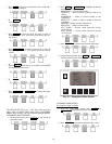
Words printed in all capital letters and in a box represent
softkeys on the CVC/ICVC control panel (e.g., ,
, , , etc.).
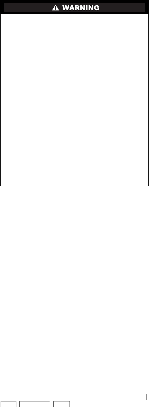
This unit uses a microprocessor control system. Do not
short or jumper between terminations on circuit boards or
modules; control or board failure may result.
Be aware of electrostatic discharge (static electricity) when
handling or making contact with circuit boards or module
connections. Always touch a chassis (grounded) part to dis-
sipate body electrostatic charge before working inside con-
trol center.
Use extreme care when handling tools near boards and
when connecting or disconnecting terminal plugs. Circuit
boards can easily be damaged. Always hold boards by the
edges and avoid touching components and connections.
This equipment uses, and can radiate, radio frequency
energy. If not installed and used in accordance with the
instruction manual, it may cause interference to radio com-
munications. It has been tested and found to comply with
the limits for a Class A computing device pursuant to Sub-
part J of Part 15 of FCC Rules, which are designed to pro-
vide reasonable protection against such interference when
operated in a commercial environment. Operation of this
equipment in a residential area is likely to cause interfer-
ence, in which case the user, at his own expense, will be
required to take whatever measures may be required to cor-
rect the interference.
Always store and transport replacement or defective boards
in anti-static shipping bag.
CCM — Chiller Control Module
CCN — Carrier Comfort Network
CCW — Counterclockwise
CVC — Chiller Visual Controller
CW — Clockwise
ECDW — Entering Condenser Water
ECW — Entering Chilled Water
EMS — Energy Management System
HGBP — Hot Gas Bypass
I/O — Input/Output
ICVC — International Chiller Visual Controller
ISM — Integrated Starter Module
LCD — Liquid Crystal Display
LCDW — Leaving Condenser Water
LCW — Leaving Chilled Water
LED — Light-Emitting Diode
OLTA — Overload Trip Amps
PIC II — Product Integrated Controls II
RLA — Rated Load Amps
SCR — Silicon Controlled Rectifier
SI — International System of Units
TXV — Thermostatic Expansion Valve
VFD — Variable Frequency Drive
ENTER
EXIT INCREASE QUIT