3 - 12
3.4.2 Creating module configuration diagrams
3 OPERATING PROCEDURE OF MELSOFT NAVIGATOR
iQ Works
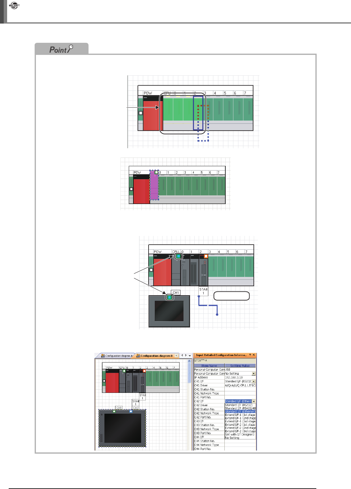
● Mounting modules
• When a module is dragged onto the base unit, the mountable area of the base unit is displayed in light green as
shown below.
• If a module is not mounted properly, the whole module is displayed in pink as shown below.
● Connection lines
When a connection line is dragged and dropped onto the Module Configuration window, the connectable ports of
each controller are displayed as shown below.
● Connection points of GOT unit
By setting parameters on the Input Detailed Configuration Information window, I/F type and number of
connectable points of GOT unit can be changed.
Mountable slots
Drag & drop
Connectable ports


