


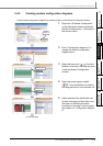
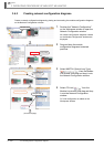
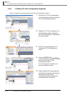

3.4.2 Creating module configuration diagrams
3 - 17
1
OVERVIEW
2
SCREEN
CONFIGURATION
3
OPERATING PROCEDURE
OF MELSOFT NAVIGATOR
4
USING SYSTEM
LABELS
5
CREATING SYSTEM
BACKUP DATA
6
USING PROGRAM
JUMP FUNCTION
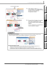
3.4 Creating System Configuration Diagram
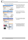
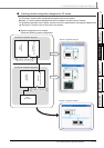
■ Creating module configuration diagrams for FX series
For FX series, create module configuration diagrams refer to this section.
Basically, FX series module configurations can be created in a similar way to Q series.
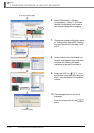
For operations that differ from Q series, and for main units, special blocks, and special adapters that
can be used in FX series, refer to the Point in this section.
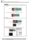
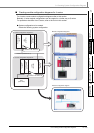
● System configuration to be created
Create the following system configuration.
(FX3UCPU)
<FX Module configuration diagramA>
Ethernet (Network No.1)
FXCPU
(FX
3UCPU)
Ethernet
special function block
<FX Module configuration diagramB>
IP address :192.168.3.38
Ethernet
special function block
FXCPU
GOT
(GOT1000)
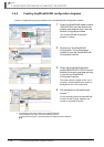
Module configuration diagram
Network configuration diagram
IP address :192.168.3.39