3.7.1 Checking system configuration
3 - 47
1
OVERVIEW
2
SCREEN
CONFIGURATION
3
OPERATING PROCEDURE
OF MELSOFT NAVIGATOR
4
USING SYSTEM
LABELS
5
CREATING SYSTEM
BACKUP DATA
6
USING PROGRAM
JUMP FUNCTION
3.7 Checking System Configuration
3.7 Checking System Configuration
This section explains a method for checking module configurations/CC-Link configurations of created system
configuration, power supply capacity, and I/O points.
3.7.1 Checking system configuration
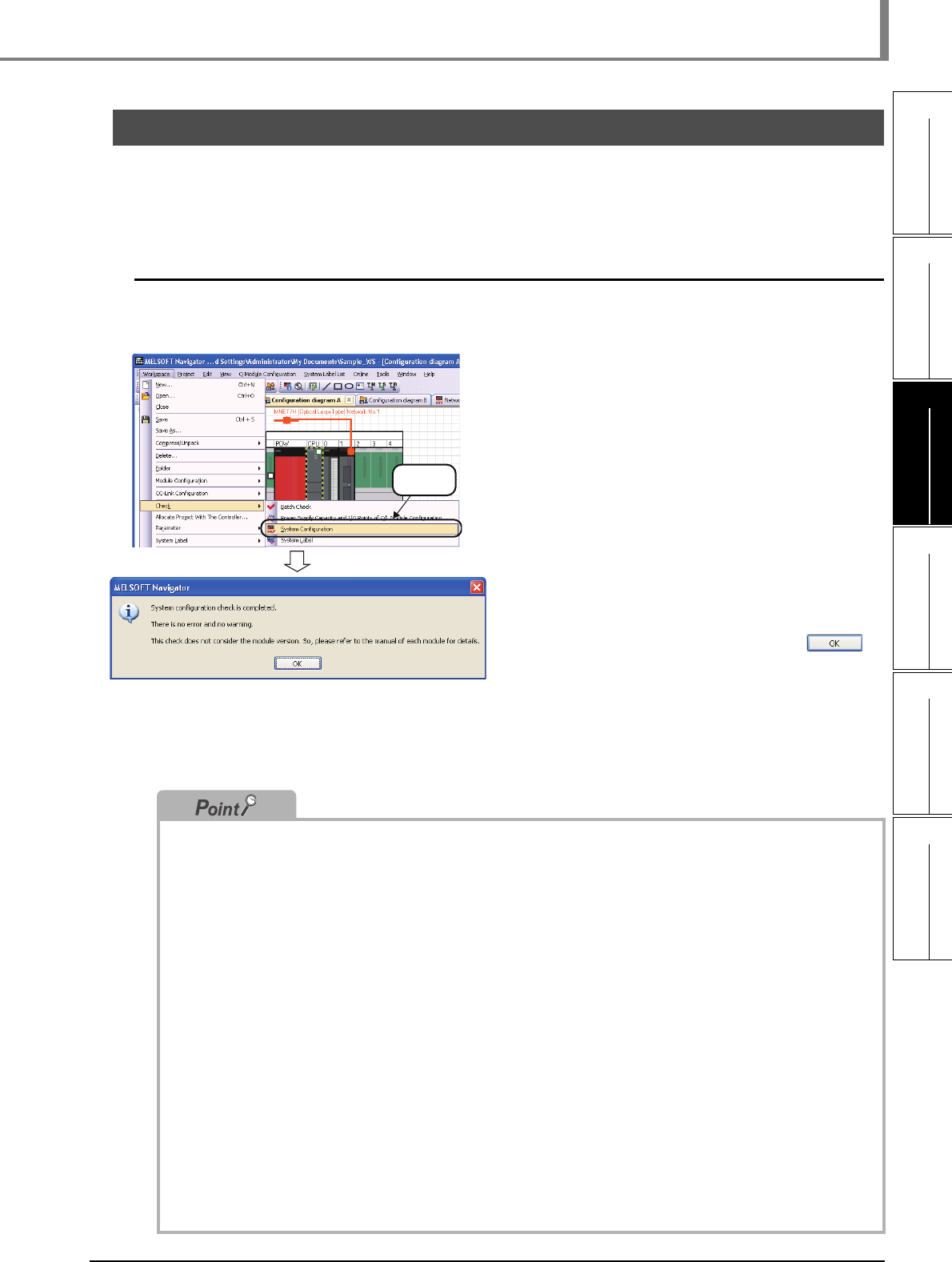
Check module configurations of created system configuration and allocated status of projects.
1. Select [Workspace] ⇒ [Check] ⇒
[System Configuration] in the menu
bar.
2. The message shown on the left is
displayed.
Read the message and click the
button.
Error or Warning is displayed when the
check result contains an error. Check the
error description on the Task List window
and correct the error.
● Check target
System configuration check function checks the following items.
• Common to Q series/L series/FX series module configurations
•Unmounted modules
•Matching of project PLC type and CPU module model name of module configuration.
•Allocation of projects in the workspace to CPU modules or other modules of module configuration.
• Q series module configuration
•Power supply mounting condition
•CPU module configuration (multiple CPU system)
•Configuration of main base unit and extension base unit or GOT
•Number of mounted modules (For details, refer to the Help function of MELSOFT Navigator.)
•Consumption current within the range
•I/O points within the range
• L series module configuration
•Power supply and END cover mounting condition
•Consumption current within the range
•I/O points within the range
• AnyWireASLINK configuration, CC-Link configuration, Ethernet configuration, and CC IE Field configuration
•Equipment configuration of AnyWireASLINK configuration, CC-Link configuration, Ethernet configuration, and
CC IE Field configuration
Note that, CPU module versions, module versions, and GOT model names are not checked.
● GOT installation
When installing the first GOT at the position more than 13.2m in distance, a bus extension connector box is
required.
Select
