


104 Installing Upgrades
www.dell.com | support.dell.com
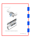
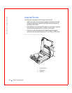
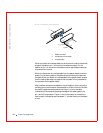
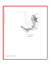
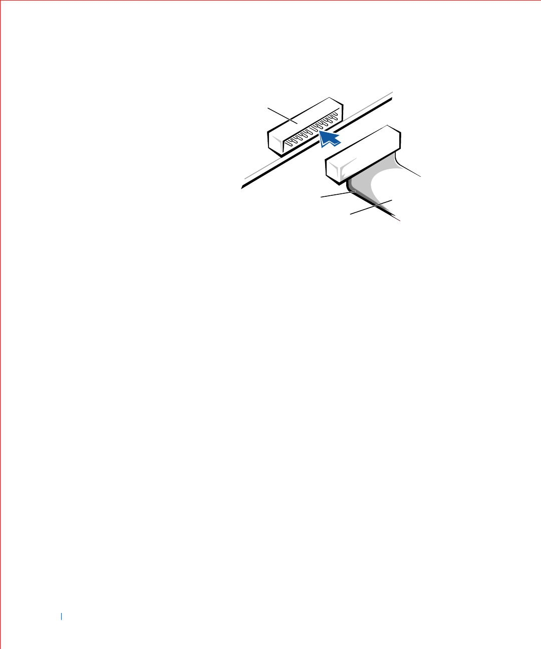
Drive Interface Connectors
When you attach the interface cable to a drive, be sure to match the colored
stripe on the cable to pin 1 of the drive’s interface connector. For the
location of pin 1 on the drive’s interface connector, see the documentation
that came with the drive.
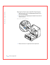
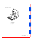
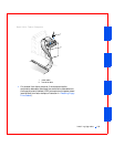
When you disconnect an interface cable from the system board, be sure to
press in on the locking tabs on the cable connector before you disconnect
the cable. When you attach an interface cable to the system board, be sure
that the locking tabs snap into place so that the cable is firmly attached to
the connector on the system board.
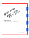
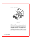
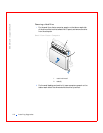
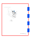
Most interface connectors are keyed for correct insertion; that is, a notch or
a missing pin on one connector matches a tab or a filled-in hole on the other
connector. Keyed connectors ensure that the pin-1 wire in the cable
(indicated by the colored stripe along one edge of the cable) goes to the
pin-1 end of the connector. The pin-1 end of a connector on a board or a
card is usually indicated by a silk-screened “1” printed directly on the board
or card.
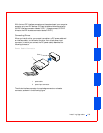
1header connector
2 colored stripe on the cable
3interface cable
1
3
2