


6-8T-268-07
6.6.2 Adding Refrigerant to System (Full Charge)
a. Evacuate unit and leave in deep vacuum. (Refer to
section 6.5.)
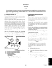
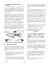
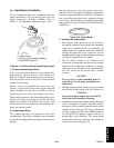
b. Place cylinder of R-134a on scale and connect
charging line from cylinder to liquid line valve.
Purge charging line at liquid line valve and then
note weight of cylinder and refrigerant.
c. Open liquid valve on cylinder. Open liquid line
valve half-way and allow the liquid refrigerant to
flow into the unit until the correct weight of
refrigerant has been added as indicated by scales.
Correct charge is noted in Table 6-6.
NOTE
It may be necessary to finish charging unit
through suction service valve in gas form, due
to pressure rise in high side of the system.
(Refer to section 6.6.3)
d. Backseat manual liquid line valve (to close off
gauge port). Close liquid valve on cylinder.
e. Start unit in cooling m ode. Run approximately 10
minutes and check the refrigerant charge. (Refer to
section 6.6.1.)
6.6.3 Adding Refrigerant to System (Partial
Charge)
a. Examine the unit refrigerant system for any
evidence of leaks. Repair as necessary. (Refer to
section 6.4.)
b. Maintain the conditions outlined in section 6. 6. 1.
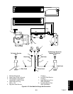
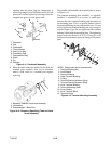
c. Fully backseat (to close off gauge port) the suction
service valve (see Figure 2-5) and remove the
service port cap.
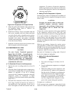
d. Connect charging line between suction service
valve port and cylinder of refrigerant R-134a. Open
VAPOR valve.
e. Partially frontseat (turn clockwise) the suction
service valve and slowly add charge until the
refrigerant appears at the proper level (refer to
section 6.6.1).
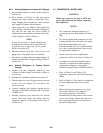
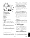
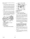
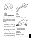
6.7 COMPRESSOR -- MODEL 06DR
WARNING
Make sure power to the unit is OFF and
power plug disconnected before replacing
the compressor.
NOTES
S The compressor should not operate in a
vacuum greater than 500 mm Hg (20 inches
Hg).
S The service replacement compressor is sold
without shutoff valves (but with valve pads),
and without terminal box and cover.
Customer should retain the original terminal
box, cover, and high pressure switch for use
on replacement compressor.
S Check oil level in service replacement
compressor. (Refer to sections 2.2 and 6.10.)
S A compressor terminal wiring kit must be
ordered as a separate item when ordering
replacement compressor. Appropriate
installation instructions are included with kit.
S Refer to Table 6-4 and Table 6-5 for
applicable compressor wear limits and torque
values.
S Refer to Figure 6-34 for charts on compressor
pressure-temperature and motor current
curves.
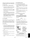
S When servicing the compressor, you must
first identify whether it is a single- or
two-speed compressor. This can be
determined by the bolt pattern of the suction
service valve flange. Single-speed has a two
bolt configuration and the two-speed has a
four bolt configuration.