


SECTION 4
4-1 T-268-07
SECTION 4
OPERAT ION
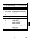
4.1 PRE-TRIP INSPECTION (Before Starting)
WARNING
Beware of unannounced starting of the
evaporator and condenser fans.
a. If container is empty, check inside for the
following:
1. Check channels or “T”bars on floor for cleanliness.
Channels must be free of debris for proper air
circulation.
2. Check container panels, insulation and door seals
for damage. Effect permanent or temporary r epairs.
3. Visually check evaporator fan assembly clamp
bolts for proper securement (refer to section 6.15).
4. Check for dirt or grease on e vaporator fan or fan
deck and clean if necessary.
5. Check evaporator coil for cleanliness or
obstructions. Wash with fresh water.
(Refer to section 6.13.)
6. Check defrost drain pans a nd d rain lines for
obstructionsand clearif necessary. Wash with fresh
water.
7. Check panels on refrigeration unit for loose bolts
and condition of panels. Make sure T.I.R. devices
are in place on access panels.
b. Check condenser coil for cleanliness. Wash with
fresh water. (Refer to section 6.17.)
c. Check position of fresh air makeup vent cover.
Operator must determine if fresh air makeup vent
cover is to be opened or closed.
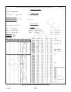
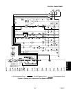
d. Open Partlow recording thermometer door (if so
equipped) and do the following:
1. Manually wind clock on key wound recording
thermometer (key is located in a clip.) KEY MUST
STAY WITH THE THERMOMETER. Check
battery on battery powered recording thermometer.
2. Lift stylus(pen) by pulling the marking tip outward
until the stylus arm snaps into it’s retracted
position.
3. Install new chart on recording thermometer making
sure chart is under the four corner tabs. Lower the
stylus until stylus has made contact with the chart.
Then close and secure door.
e. Open Saginomiya record ing thermomete r door (if so
equipped) and do the following:
1. Chec k Chart drive batte ry condition.
(Refer to section 6.20.)
2. Lift stylus (pen ) by pushing in the stylus lifter and
rota ting the lifter cloc kwise (ra ising stylus at same
time) until lifter locks in position.
3. Install new chart on recording thermometer making
sure cha rt is unde r the four corner tabs. Release stylus
lifter by pushing down and ro tating lifter
counter clockwise until stylus lifter locks in position
and stylus has made contact with chart. Then close
door.
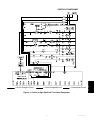
f. Open control box door. Check for loose electrical
connections or hardware.
g. Check color of moisture-liquid i ndicator.
h. Check oil level in compressor sight glass.
i. Start refrigeration unit. (Refer to section 4.3.)