


6-26T-268-07
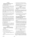
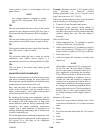
Ambient Temperature
Cold Coil
10_ F 6.45 ohms
40_ F 6.90 ohms
70_ F 7.40 ohms
100_ F 7.90 ohms
4. Plug in the connector for the modulation valve.
NOTE
A cold coil is a coil which has not been
operating and is assumed to be at ambient
temperature. Hot coils, taken after the unit has
been operating in deep modulation for a long
period of time, m ay give higher resistance
readings.
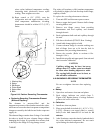
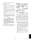
1
2
3
4
5
6
7
8
9
10
11
12
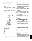
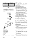
1. Coil Nut
2. Coil Nut O-ring
3. Coil Housing
4. Solenoid Coil Sleeve
5. Solenoid Coil
6. Enclosing Tube Assy.
7. Piston
8. Top Return Spring
9. Valve Body
10. Bottom Return Spring
11. Filter
12. Schrader Valve
Figure 6-28. Suction Modulation Valve (SMV)
b. Replacing the Coil
Remove locking nut and remove coil after
disconnecting wiring. When replacing nut, torque to a
value of 0.41 mkg (3 ft-lb).
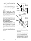
c. To Replace Valve
1. Pump down the unit per section 6.3.
2. Remove two bolts from suction service valve.
3. Melt solder at modulating valve connection and
rotatevalve and tubing enough to clear compressor.
Remove valve and tubing. Replace defective
suction modulation valve, being careful to wrap
body of replacement valve with a wet cloth while
brazing (inert gas brazing procedures MUST be
used only). The coil need not be removed.
4. Install new suction service valve gasket and install
bolts in suction service valve. Torque to a value of
2.77 to 4.15 mkg (20 to 30 ft/lb).
5. Solder all connections and leak check same.
6. Dehydrate and evacuate the unit per section 6.5.
Add refrigerant charge per section 6.6.
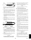
6.26 THERMOSTATIC EXPANSION VALVE
The thermal expansion valve is an automatic device
which maintains constant superheat of the refrigerant
gas leaving the evaporator, regardless of suction
pressure. The valve functions are: (a) automatic
response of refrigerant flow to match t he evaporator
load and (b)prevention ofliquid refrigerant enteringthe
compressor. Unless the valve is defective, it seldom
requires any maintenance other than minor periodic
maintenance as follows:
1. Make sure that the excess capillary tube is secured
to the power head assembly and wrapped with
“Presstite.”
2. Makesure that the thermal bulbis tightly securedto
the suction line and wrapped with “Presstite.”
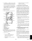
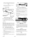
a. Rem oving E xpans ion Va lve (Se e Figur e 6-2 9)
1. Pump down the unit per section 6.3.
2. Remove insulation (Presstite) from expansion
valve bulb and power assembly and then remove
thermal bulb from the suction line.
3. Loosen flare nut and disconnect equalizing line
from expansion valve.
4. Remove capscrews and lift off power assembly and
remove cage assembly. Check for foreign material
in valve body.