


SECTION 3
3-5 T-268-07
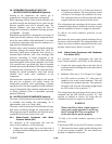
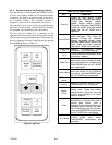
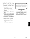
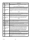
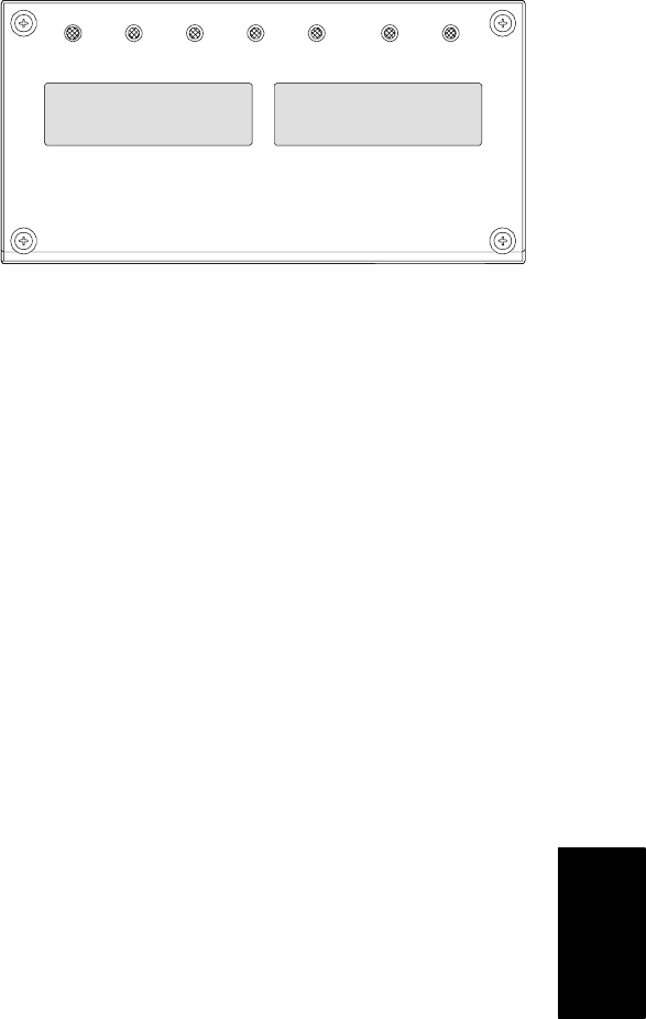
The display module (see Figure 3-2) is mounted at a 20
degree downward tilt to aid in visibility. The display
module consists of:
a. Two 25mm (1 inch) high, five digit LC D displays
which are easily viewed in direct sunlight and
backlighted for superior low-light visibility.
b. Seven Indicators:
S Cool -- White Lamp: Energized when the
refrigerant compressor is energized.
S Heat -- Orange LED: Energized when the
heaters are on, and the unit is in the heat or
defrost mode.
S Defrost -- Orange LED: Energized when the
heaters are on, and the unit is in the defrost
mode.
S In-Range -- Green LED: Energized when the
controlling tempe ra ture probe is in range.
(Supply air probe will be used for control in
the perisha ble ra nges and the re turn air probe is
used for contro l in the fr oze n range s.)
S Alarm -- Red LED: Energized when there is
an active or an inactive shutdown alarm
(AL20 to AL27) in the alarm queue.
S Supply -- Yellow LED: Energized when
supply temperature and set point are
displayed. Flashes if dehumidification or
humidification is enabled on units so
equipped.
S Return -- Yellow LED: Energized when return
temperature and set point are displayed.
COOL HEAT DEFROST INRANGE ALARM SUPPLY RETURN
SETPOINT/Code AIR TEMPERATURE/Data
Figure 3-2. Display Module
NOTE
The default display mode will show the set
point temperature (on the left display) and
controlling probe temperature (on the right
display). The controlling probe in the
perishable range will be the SUPPLY air probe
and t he controlling probe in the frozen range
will be the RETURN air probe.