


6-18T-268-07
WARNING
With power OFF discharge the capacitor
and disconnect the circuit wiring.
c. Checking the capacitor
If the capacitor is suspected of malfunction, you may
choose to simply replace it. Direct replacement requires
a capacitor of the same value. Two methods for
checking capacitor function are:
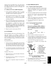
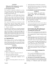
1. Volt-ohmmeter set on RX 10,000 ohms. Connect
ohmmeter leads across the capacitor terminals and
observe the meter needle. If the capacitor is good, the
needle will make a rapid swing toward zero resistance
and then gradually swing back toward a very high
resistance reading.
If the capacitor has failed open, the ohmmeter needle
will not move when the meter probes touch the
terminals. If the capacitor is shorted, the needle will
swing t o zero resistance position and stay there.
2. Capacitor analyzer
The function of the analyzer is to read the microfarad
value of a capacitor and to detect insulation breakdown
under load conditions. The important advantages of a
analyzer are its ability to locate capacitors that have
failed to hold their microfarad ratings, or those that are
breaking down internally during operation. It is also
useful in identifying capacitors when their microfarad
rating marks have become unreadable.
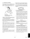
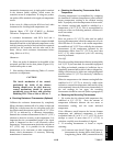
6.17 CONDENSER COIL
The condenser consists of a series of parallel copper
tubes expanded into copper fins. The condenser coil
mustbe cleanedwith freshwaterorsteam sotheairflow
is not restricted. Fan rotation is counterclockwise when
viewed from shaft end of motor.
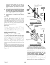
WARNING
Do not open the condenser fan grille before
turning power OFF and disconnecting
power plug.
To Replace Condenser Coil:
a. Remove the refrigerant charge per section 6.3.
b. Remove the condenser coil guard.
c. Unsolder discharge line and remove the line to the
receiver or water-cooled condenser (if so
equipped).
d. Remove coil mounting hardware and remove the
coil.
e. Install replacement coil and solder connections.
f. Leak-check the coil per section 6.4. Evacuate the
unit per section 6.5, then charge the unit with
refrigerant per section 6.6.1.
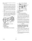
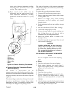
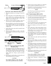
6.18 CONDENSER FAN AND MOTOR ASSEMBLY
WARNING
Do not open condenser fan grille before
turning power OFF and disconnecting
power plug.
The condenser fan rotates counter-clockwise (viewed
from front of unit), pulls air through the the condenser
coil,anddischargeshorizontallythroughthe front ofthe
unit. To replace motor assembly:
a. Open condenser fan screen guard.
b. Loosen two square head set screws on fan. (Thread
sealer ha s been ap plied to set s crews atinstallation.)
Disconnect wiring from motor junction box.
CAUTION
Take necessary steps (p lace plywood over
coil or use sling on motor) to prevent motor
from falling into condenser coil.
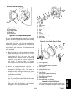
c. Remove motor mounting hardware and replace the
motor.It isrecommendedthatnewlocknuts beused
when replacing motor. Connect wiring per wiring
diagram.
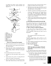
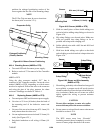
d. Install fan loosely on motor shaft (hub side in). DO
NOT USE FORCE. If necessary, tap the hub only,
not the hub nuts or bolts. Install venturi. Apply
“Loctite H” to fan set screws. Adjust fan within
venturi so that the outer edge of the fan projects 3.2
to 6.4 mm (3/16” ¦1/16”) back from edge of the
venturi. Spin fan by hand to check clearance.
e. Close and secure condenser fan screen guard.
f. Apply power to unit and check fan rotation. If fan
motor rotates backward, reverse wire numbers 5
and 8.
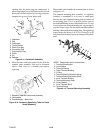
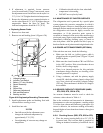
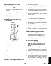
6.19 PARTLOW RECORDING THERMOMETER
NOTE
The Controller/DataCORDER return air probe
is located adjacent to the Partlow bulb, and can
be used to calibrate the chart recorder.
a. Instruments for Checking Bulb Temperature
Therecordingthermometermaybe optionally equipped
with one or two Simpson accessories (#344 units), each
consisting of a thermistor probe and receptacle