


SECTION 6
6-25 T-268-07
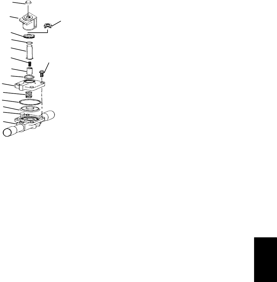
6.24 SUCTION SOLENOID VALVE (SSV)
a. Replacing the Coil
NOTE
The coil may be replaced without removing the
refrigerant.
1. Disconnect leads by unplugging the connector.
Remove snap cap or locknut. Lift off coil. (See
Figure 6-27)
2. Verify coil type, voltage and frequency of old and
new coil. This information appears on the coil
housing.
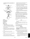
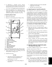
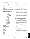
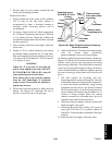
b. Replacing Valve Internal Parts -- Alco
(See Figure 6-27)
10
11
12
13
14
15
1
2
5
6
7
4
8
9
16
3
1. Snap Cap
2. Coil
3. Installation/Removal Tool
4. Enclosing Tube Collar
5. O-Ring
6. Enclosing Tube
7. Spring
8. Plunger
9. Gasket
10. Top Plate
11. Capscrews
12. Spring
13. Gasket
14. Diaphragm
15. O-Ring
16. Body
Fig ure 6-27. Suction Solenoid Valve (SSV) -- Alco
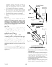
1. Pump down the unit. (Refer to section 6.3.)
2. Remove snap cap and coil.
3. Removeenclosing tube collar (item 4, Figure 6-27)
using installation/removalt ool supplied withrepair
kit(item3).
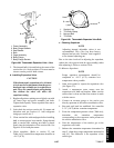
4. Checkplunger for restriction dueto: (a) corroded or
worn parts; (b) foreign material lodged in valve; (c)
bent or dented enclosing tube.
5. Remove top plate, diaphragm spring, diaphragm
and body gaskets.
6. Install new parts, assemble in reverse order of
disassembly.
7. Torque the four capscrews to 40 inch-pounds.
8. Do not overtighten enclosing tube assembly.
Torque to a value of 1.15 mkg (100 inch pounds).
9. Remove supplied i nstallation/removal tool. Install
coil, and snap cap.
10. Dehydrate and evacuate the system. (Refer t o
section6. 5) Charge unitwith refrigerant per section
6.6.1.
11. Plug in the connector. Start unit and check
operation.
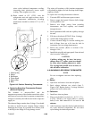
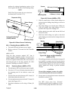
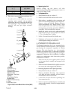
6.25 SUCTION MODULATION VALVE (SMV)
NOTE
When repairing suction modulation valve with
the enclosing tube kit (CTD P/N 14-50021-01)
be sure not to remove items 7, 8 & 10. (See
Figure 6-28) Proper alignment of these items is
achieved only at the factory.
a. Coil Checkout Procedure
WARNING
Make sure power to the unit is OFF and
power plug disconnected before replacing
the coil.
1. Disconnect the suction modulation valve coil wires
by unplugging the connector (Refer to section 5).
2. Using a reliable digital ohmmeter, test each lead’s
resistance to ground. If the resistance indicates a
ground short is present, inspect thelength of wiring
for damaged or exposed wires. Replace where
necessary.
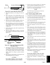
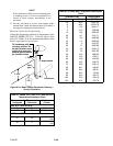
3. Setting the digital ohmmeter for low range, check
coil’s resistance. If coil’s resistance is below five
ohms, replacement is recommended. New coils
have an approximate resistance of 7.6 ohms at 25_
C(77_ F). The chart below gives the resistance of a
new coil at various ambient temperatures.