


SECTION 4
4-3 T-268-07
IfAL55 isactive,meaningthat the DataCORDER(DC)
functionality is no longer active (DC configuration
variable off), the Controller will act as a four probe
configured system during probe checks. The only
differences will be that the Controller Function Codes
Cd38 and Cd39 will become enabled thus allowing
access to the secondary probe readings since the DC
functions, codes and alarms have become deactivated.
Controller alarms AL70 and AL71 will replace DC
alarms AL70 and AL71 respectively for the secondary
probes.
If theunit isconfiguredfor standard(Std) “ProbeCheck
Logic,” a probe check will be run as a part of every
normal defrost.
If the unit is configured for special (SPEC) “Probe
Check Logic,” a probe check will not be run as a part of
a normal defrost, but only as a part of a defrost initiated
due to a diagnostic reading outside of the limits as
outlined above under “special.”
c. P robe Chec k
During a defrost cycle that includes a probe check, after
the heaters turn off, the evaporator motors will be
energized for an additional eight minutes afterwhich all
the primary/secondary probes will be compared to a set
of predetermined limits.
The defrost indicator will remain on throughout this
period.
Any probe(s) determined to be outside the limits will
cause the appropriate alarm code(s) to be displayed to
identify which probe(s) needs to be replaced.
The limits used during a probe check are tighter than
those used for thediagnostic criteriat o ensureaccurate
detection of a faulty probe(s).
NOTES
S Be aware that probe check and probe
diagnostics are two separate functions. The
function of the diagnostic logic is to alert the
microprocessor of a discrepancy with the
control probe(s). The function of the probe
check is to determine what probe(s) is in
error.
S The P5 Pre-Trip test must be run to inactivate
alarms (refer to section 3.2.1).
4.4 .3 C ooling -- Contr oller Set BELOW --1 0_C
(+14_F), or --5_C(+23_F) optionally
NOTES
S The suction solenoid valve (SS V) will be
open t o increase the refrigerant flow rate and
cooling capacity unless SSV override is
activated.
S The suction modulation valve (SMV) is
100% open.
S The evaporator motors run in low speed.
S The compressor runs in high speed.
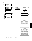
S Refer to Figure 3-7 for a description of the
dual speed compressor change logic.
When the return air temperature decreases to 0.2_C
(0.4_F) below set point, relays TD and TNde-energize.
This results in de-energizing the compressor and
condenser fan motor. Also, the cool light is
de-energized. The evaporator fan motors continue to
run to circulate air throughout the container.
When the return air temperature increases to 0.2_C
(0.4_F) above set point, and providing a sufficient
off-time period has elapsed, relays TD and TN energize
to restart thecompressorand condenser fan motor. Also
at this time, the cool light is illuminated.
4.4.4 Controller Set ABOVE --10_C(+14_F), or
-- 5 _C(+23_F) optionally
NOTE
Evaporator fan m otors will run in high speed.
(Contactor EF energized.)
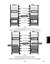
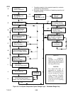
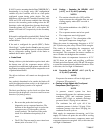
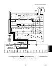
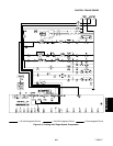
a. Cooling in High Speed with Two -Speed
Compressor (See Figure 4-1.)
NOTE
A pressure control system has been
incorporated by means of a condenser pressure
transducer (CPT) and condenser pressure
control (CPC) logic to maintain discharge
pressures above 130 psig in low ambients.
The condenser fan will cycle off if the
condenser pressure is below 130 psig. If the
condenser pressure rises above 200 psig, the
condenser fan will cycle on.
With supply air temperature decreasing, and if the
supply air is above set point, the unit will be cooling
with the condenser fan motor, compressor motor and
evaporator fan motors energized. Also, at this time, the
cool light is illuminated.