


2-2T-268-07
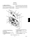
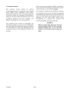
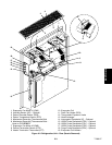
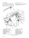
b. Evaporator Section
The evaporator section contains the optional
mechanical temperature recording bulb, return recorder
sensor (RRS), return temperature sensor (RTS),
thermostatic expansion valve, dual-speed evaporator
fan motors and fans (2), evaporator coil and heaters,
drain pan and heater, defrost termination sensor, heat
termination thermostat, and heat exchanger. See
Figure 2-2 and Figure 2-5 for sensor locations.
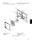
The evaporator fans circulate air throughout the
container by pulling air in the top of the refrigeration
unit, directing the air through the evaporator coil where
it is either heated or cooled, and discharging the air
through the bottom of the refrigeration unit into the
container.
When transporting perishable (chilled) commodities,
the fan motors will normally be in high speed above
-- 1 0 _C(+14_F), or --5_C(+23_F) optionally.
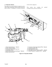
The evaporator coil heaters are accessible by removing
the front lower access panel. The defrost termination
sensor (DTS) is located on the c oil center tube sheet and
may be servicedby removing theupper rear panel, orby
removing the left front upper access panel,
disconnecting the evaporator fan connector and
reaching through the access panel opening.
WARNING
Before servicing unit, make sure the unit
circuit breakers (CB-1 & CB-2) and the
start-stop switch (ST) are in the OFF
position. Also disconnect power plug and
cable.