


SECTION 2
2-7 T-268-07
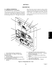
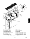
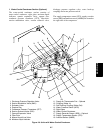
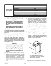
f. Water-Cooled Condenser Section (Optional)
The water-cooled condenser section consists of
water-cooled condenser, sight glass, moisture-liquid
indicator, quench expansion valve, rupture disc,
condenser pressure transducer (CPT), filter-drier,
suction m odulation valve, suction solenoid valve,
discharge pressure regulator valve, water hook-up
couplings and water pressure switch.
The supply temperature sensor (STS), supply recorder
sensor (S RS) a ndambient sensor (AMBS) are located at
the right side of the compressor.
17
1
2
10
5
6
13
14
11
12
9
8
7
15
16
3
4
18
19
1. Discharge Pressure Regulator Valve
2. Suction Modulation Valve (SMV)
3. Schrader Valve
4. Rupture Disc
5. Condenser Pressure Transducer (CPT)
6. Suction Solenoid Valve (SSV)
7. Quench Expansion Valve
8. Filter-Drier
9. Manual Liquid Line Valve
10. Moisture-Liquid Indicator
11. Supply Air Thermometer Port -- Optional
12. Coupling (Water In)
13. Self Draining Coupling (Water Out)
14. Water Pressure Switch (WPS)
15. Sight Glass
16. Water-Cooled Condenser
17. Supply Recorder Sensor (SRS) -- Optional
18. Supply Temperature Sensor (STS)
19. Ambient Sensor (AMBS)
Figure 2-6. Units with Water-Cooled Condenser