


6-16T-268-07
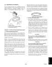
f. Open cylinder valve. S lowly close bleed-off valve
to increase pressure on switch. The switch should
open at a static pressure upto 25 kg/cm@ (350 psig).
If alight isused, light will goout. If an ohmmeter is
used, the meter will indicate open circuits.
g. Slowly open bleed-off valve to decrease the
pressure. The switch will close at 18 kg/cm@ (250
psig).
6.13 EVAPORATOR COIL AND HEATER
ASSEMBLY
The evaporator section, including the coil, should be
cleaned regularly. The preferred cleaning fluid is fresh
water or steam. Another possible cleaner is Oakite 202
or similar, following manufacturer’s instructions.
The two drain pan hoses connected to the drain pan are
routed behind the condenser fan motor and compressor.
The drain pan line(s) must be open to ensure adequate
drainage.
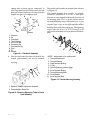
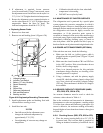
To Replace the Evaporator Coil:
a. Pump unit down. (See Figure 2-5, refer to section
6.3.)
b. With power OFF and power plug removed, remove
the screws securing the panel covering the
evaporator section (upper panel).
c. Disconnect the defrost heater wiring.
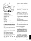
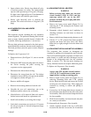
d. Disconnect the sensor from the coil. The defrost
termination sensor (DTS) is located on the middle
coil support as shown in Figure 2-2.
e. Remove middle coil support.
f. R emove the mounting hardware from the coil.
g. Unsolder the two coil connections, one at the
distributor and the other at the coil header.
h. After defective coil is removed from unit, remove
defrost heaters and install on replacement coil.
i. Install coil assembly by reversing above steps.
j. Leak check connections per section 6.4. Evacuate
the unit per section 6.5 and add refrigerant charge
per section 6.6.2.
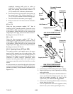
6.14 EVAPORATOR COIL HEATERS
WARNING
Before servicing unit, make sure the unit
circuit breakers (CB-1 & CB-2) and the
start-stop switch (ST) are in the OFF
position, and that the power plug and cable
are disconnected.
a. Remove the lower access panel (Figure 2-1) by
removing the T.I.R. locking device lockwire and
mounting screws.
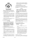
b. Determine which heater(s) need replacing by
checking resistance on each heater as shown in
section 1.4.e.
c. Remove hold-down clamp securing heaters to coil.
d. Lift the “U” or “W” portion of the heater (with the
opposite end down and away from coil). Move
heater left (or right) enough to clear the heater end
support.
6.15 EVAPORATOR FAN AND MOTOR ASSEMBLY
The evaporator fans circulate air throughout the
container by pulling air in through the t op of the unit.
The air is forced through the evaporator coil where it is
either heated or cooled and then discharged out the
bottom of the refrigeration unit into the container.
(Refer to section 2.3.) The fan motor bearings are
factory lubricated and do not require additional grease.
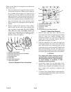
To Replace the Evaporator Fan Assembly:
WARNING
Always turn OFF the unit circuit breakers
(CB-1 & CB-2) and disconnect main power
supply before working on moving parts.
a. Remove upper access panel (see Figure 2-1) by
removing mounting bolts and T.I.R. locking
device. Reach inside of u nit and remove theTy-Rap
securing the wire harness loop. Then unplug the
connector by twisting to unlock and pulling to
separate.
b. Loosen four 1/4-20 clamp bolts that are located on
theundersideofthe fandeckat thesidesof theofthe
fan assembly. Slide the loosened clamps back from
the fan assembly.
c. Slide the fan assembly out from t he unit and place
on a sturdy work surface.
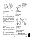
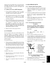
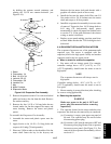
To disassemble the Evaporator Fan Assembly:
1. Attach a spanner wrench to the two 1/4-20 holes
located in the fan hub. Loosen the 5/8-18 shaft nut