


2-8T-268-07
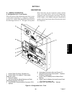
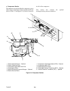
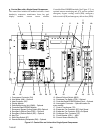
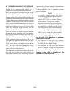
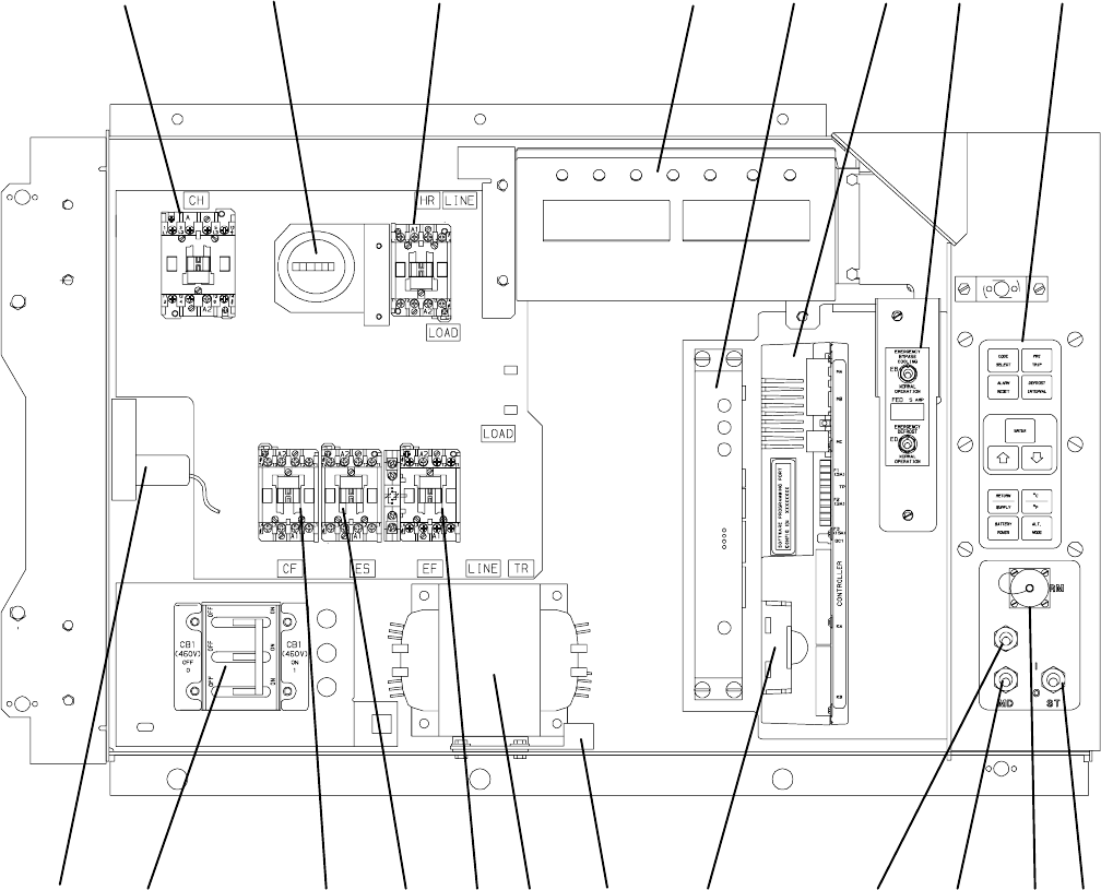
g. Control Box with a Single-Speed Compressor
The control box includes the manual switches, circuit
breaker(s), contactors, transformer, fuses, key pad,
display module, current sensor module,
Controller/DataCORDER module (See Figure 2-7), an
optional remote monitoring unit (CI), and an optional
emergency bypass cooling switch (EB), emergency
defrost switch (ED) and emergency defrost fuse (FED).
151718 16
1345610
1
1
13 1219202122
7
14
8
9
2
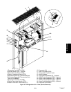
1. Compressor Contactor (CH)
2. Hour Meter (HM) -- Optional
3. Heat Contactor (HR)
4. Display Module
5. Remote Monitoring Unit (RMU) -- Optional
6. Controller/DataCORDER Module
7. Emergency Bypass Cooling Switch (EB)--Optional
8. Emergency Defrost Fuse (FED) -- Optional
9. Emergency Defrost Switch (ED) -- Optional
10. Key Pad
11. Start-Stop Switch (ST)
12. Remote Monitoring Receptacle (RM) -- Optional
13. Manual Defrost Switch (MDS)
14. Condenser Fan Switch (CFS) -- Optional
15. Controller/DataCORDER Battery Pack -- Optional
16. Interrogator Connector -- Optional location for
some models
17. Control Transformer (TR)
18. Evaporator Fan Contactor (EF) High Speed
19. Evaporator Fan Contactor (ES) Low Speed
20. Condenser Fan Contactor (CF)
21. Circuit Breaker (CB-1) -- 460V
22. Current Sensor Module (CS)
Figure 2-7. Control Box on Units with a Single- Speed Compressor