


SECTION 3
3-1 T-268-07
SECTION 3
MICROPROCESSOR
3.1 MICRO-LINK 2i CONTROLLER MODULE
122
6
78
342 225
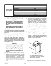
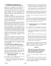
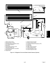
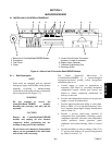
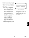
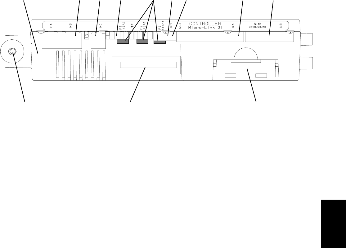
1. Micro-Link 2i Controller/DataCORDER Module
2. Connectors
3. Test Points
4. Fuses
5. Control Circuit Power Connection
(Location: In back of connector)
6. Battery Pack (Optional)
7. Software Programming Port
8. Mounting Screw
Figure 3-1. Micro -Link 2i Controller/DataCORDER Module
3.1.1 Brief Description
NOTE
Some units are equipped with an optional
emergency bypass switch (EB), which permits
manually overriding a malfunctioning
Controllerby locking theunit into acontinuous
full cooling mode (see Fi gure 2-7).
WARNING
Do not attempt to service the
Controller/DataCORDER module.
Breaking the warranty seal will void the
warranty.
CAUTION
Remove the Controller/DataCORDER
module and unplug all wire harness
connectors before performing any arc
welding on any part of the container.
Do not remove wire harnesses from module
unless you are grounded to the unit frame
with a static safe wrist strap.
The Carrier T ransicold Micro-Link 2 i
Controller/DataCORDER is a custom-designed
microprocessor-based module which incorporates
embedded software to:
a. Control supply or return air temperature to
extremely tight limits by providing modulated
refrigeration control, electric heat control and
defrost to ensure continuous conditioned air
delivery to the load.
b. Provide dual independent readouts of set point and
supply or return air temperatures.
c. Provide digital readout and ability to select data.
Refer to Table 3-3 for Controller Function Codes.
For Controller alarm digital display identification
refer to Table 3-4.
d. Provide a pre-trip step-by-step checkout of
refrigeration unit performance including: proper
component operation, electronic and refrigeration
control operation, heater operation, probe
calibration and current limiting. Refer to section
3.2.
e. Provide the ability to select or change Codes 27 to
37 and set point without AC power being hooked
up.Refertosection3.1.4.