


SECTION 6
6-13 T-268-07
6.9 COMPRESSOR REASSEMBLY
To clean compressor parts, use a suitable solvent with
proper precautions. Coat all moving parts with the
proper compressor oil before assembly. Refer to
Table 6-5 for applicable compressor torque values.
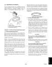
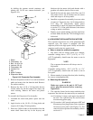
1
2
3
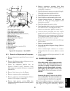
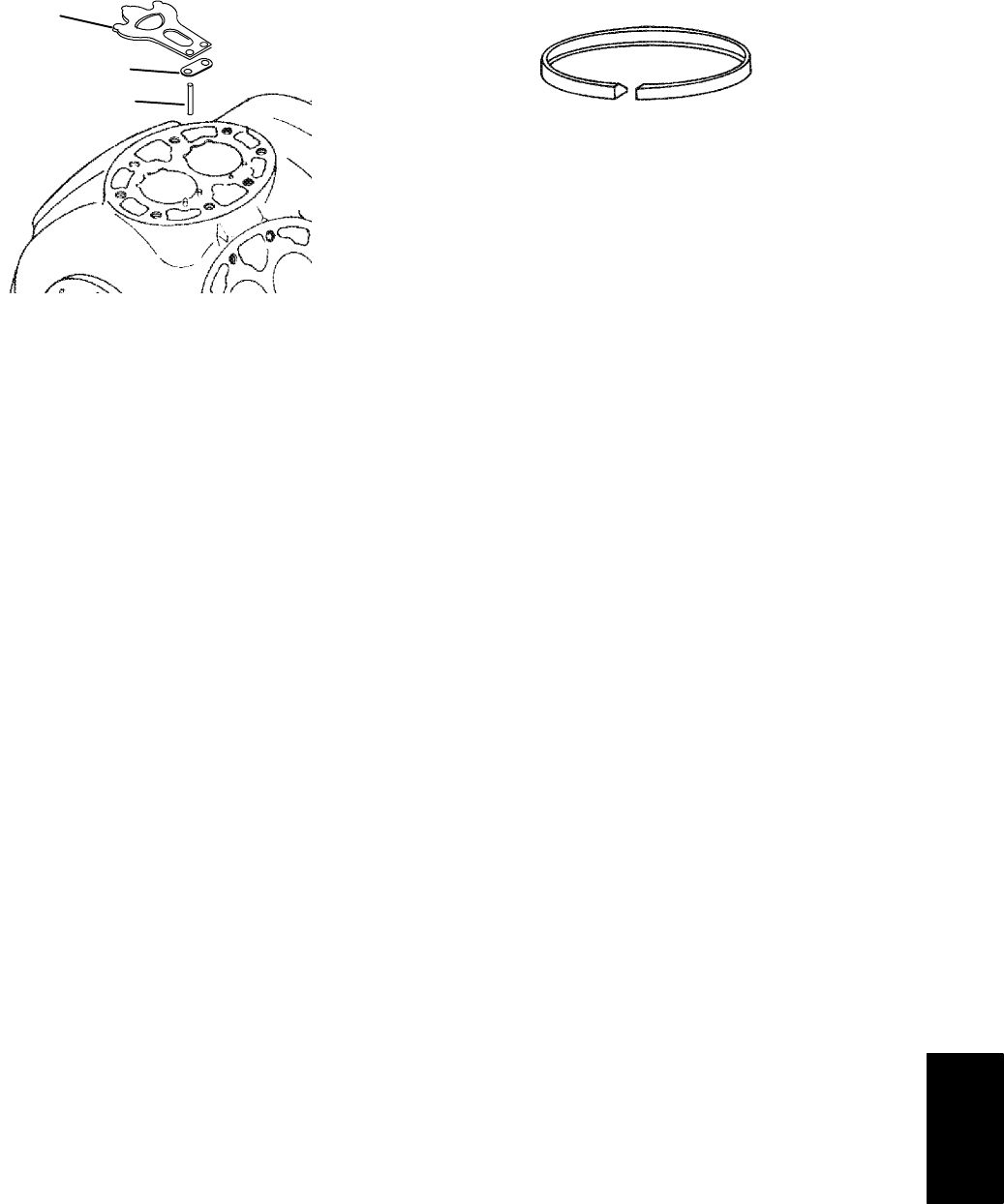
1. Suction Valve
2. Suction Valve Positioning Spring
3. Valve Plate Dowel Pin
Figure 6-14. Suction Valve & Positioning Springs
a. Suction and Discharge Valves
If the valve seats l ook damaged or worn, replace valve
plate assembly. Always use new valves because it is
difficult to reinstall used discharge valves so that they
will seat as before removal. Any valve wear will cause
leakage for this reason.
Suction valves are positioned by dowel pins (see
Figure 6-14) and will assume their original position
when reinstalled. No two valves are likely to wear in
exactly the same way. Never interchange used valves.
Do not omit the suction valve positioning springs. (See
Figure 6-14.) Place the springs so that the ends bear
against the cylinder deck (middle bowed away from
cylinderdeck).Usenewgasketswhen reinstallingvalve
plates and cylinder heads.
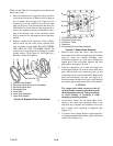
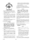
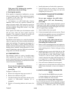
b. Compression Rings
The compression ring is chamfered on the inside
circumference. This ring is installed with the chamfer
toward thetop. Stagger thering end gaps so they arenot
aligned.
The gap between the ends of the piston rings can be
checkedwithafeelergaugebyinserting thering intothe
piston bore approximatelyone inch below the top ofthe
bore. Square the ring in the bore by pushing it slightly
with a piston. The maximum and minimum allowable
ring gaps are0.33 and 0.127 mm (0.013 and 0.005 inch)
respectively.
Figure 6-15. Piston Rings
c. Installing the Components
1. Push pistons from the inside of the crankcase
through thecylinders, being careful not to break the
rings. Place chamfered side of connecting rod
against radius of crankpins. Install the crankshaft
through the pump end of the compressor. Do not
damagemain bearings. Install matchingconnecting
rod caps through bottom cover plate.
2. The oil screen (located in the bottom of the
crankcase), is connected to the inlet of t he o il pump.
Whenever the compressor crankcase is opened,
inspect the screen for holes or an accumulation of
dirt. The screen can be cleaned with a suitable
solvent.
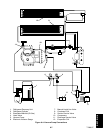
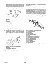
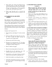
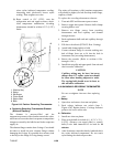
CAUTION
The set screw on the crankshaft must be
removed for the oil pump installation (see
Figure 6-8).
3. Installthe pumpend thrustwasher onthe twodowel
pins located on the bearing head. (See Figure 6-8)
CAUTION
Ensure that thrust washer does not fall off
dowel pins while installing oil pump.
4. Install the bearing head assembly with a new g asket
on the compressor crankshaft. Carefully push oil
pump on by hand, ensuring that the thrust washer
remains on the dowel pins. The tang on the end of
the drive engages the slot in the crankshaft, and the
oil inlet port on the pump i s aligned with the oil
pickup tube in the crankcase. The pump should
mount flush with the crankcase and should be
oriented as shown in Figure 6-16.