


SECTION 6
6-1 T-268-07
SECTION 6
SERVICE
NOTE
Toavoid damageto theearth’s ozonelayer, usearefrigerantrecovery systemwheneverremoving refrigerant.
When working with refrigerants you must comply with all local government environmental laws. In the
U.S.A., refer to EPA section 608.
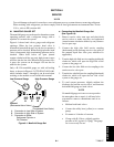
6.1 MANIFOLD GAUGE SET
Themanifoldgaugeset can beusedto determinesystem
operating pressure, add a refrigerant charge, and to
equalize or evacuate the system.
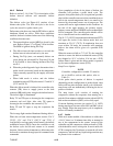
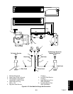
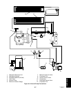
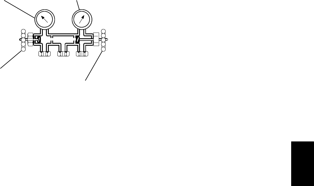
Figure 6-1 shows hand valves, gauges and refrigerant
openings. When the low pressure hand valve is
frontseated (turned all the way in), the low (evaporator)
pressure can be checked. When the high pressure hand
valve is frontseated, high (condensing) pressure can be
checked. When both valves are open ( turned
counter-clockwise all the way out), high pressure vapor
will flow intothelow side.When thelow pressurevalve
is open, the system can be charged. Oil can also be
added to the system.
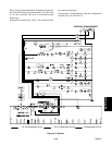
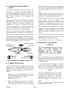
Only a R-134a manifold gauge set with self-sealing
hoses, as shown in Figure 6-2 (CTD P/N 07-00294-00,
which includes items 1 t hrough 6) can be used when
working on the models covered within this manual.
Opened
(BackseatedHandValve)
Closed
(Frontseated Hand Valve)
Low Pressure Gauge High Pressure Gaug
e
ABC
A. Connection to Low Side of System
B. Connection to High Side of System
C. Connection to Either:
Refrigerant Cylinder or
Oil Container
Figure 6-1. Manifold Gauge Set
a. Connecting the Manifold Gauge Set
(See Figure 6-2)
1. Remove service valve stem caps and check both
service valves to make sure they are backseated
(turnedcounter-clockwiseall thewayout).Remove
service port caps.
2. Connect the high side field service coupling
(backseated) to the discharge service valve port (or
the manual liquid line valve port, whichever i s
applicable).
3. Turn the high side field servicecoupling (red knob)
clockwise, which will open the high side of the
system to the gauge set.
4. Connect the low side field service coupling t o the
suction service valve port.
5. Turn thelow sidefield servicecoupling (blueknob)
clockwise, which will open the low side of the
system to the gauge set.
6. To read system pressures: slightly midseat the
discharge and suction service valves, and frontseat
both manifold gauge set hand valves.
NOTE
Ifamanifoldgaugeset isnew orwas exposedto
the atmosphere due to repair, it will need to be
evacuated to remove contaminants and air as
follows:
S Midseat both hand valves.
S Connect the utility hose (yellow) to a vacuum
pump.
S Evacuate to 10 inches of vacuum.
S Charge with R-134a to a slightly positive
pressure of 0.1 kg/cm@ (1.0 psig). The gauge
set is now ready for use.