


3-4T-268-07
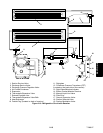
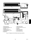
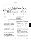
3.1.3 General Layout of the Controller Section
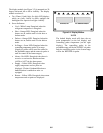
The Micro-Link 2i Controller/DataCORDER consists
of a key pad, display module and Controller module.
Connectors are used to attach the wiring of the unit to
the Controller m odule. The Controller module is
designed to permit ease of installation and removal.
All control functions are accessed by key pad selections
and viewed on the display module which are designed
for optimum user friendliness and convenience.
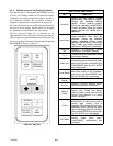
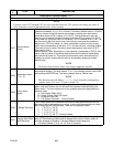
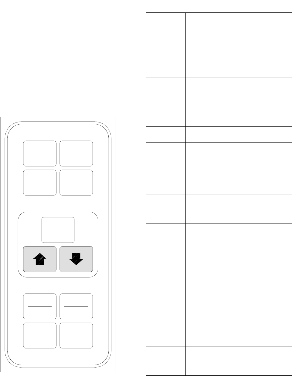
The key pad (see Figure 3-1) is mounted on the
right-hand side of the control box. The key pad consists
of eleven push-energized membrane switches that actas
the user’s interface with the Controller and the optional
DataCORDER. Refer to Table 3-2.
ENTER
BATTERY
POWER
DEFROST
INTERVAL
CODE
SELECT
PRE
TRIP
ALARM
LIST
ALT.
MODE
RETURN
SUPPLY
_C
_F
Figure 3- 1. K ey Pad
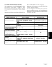
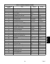
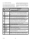
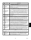
Table 3-2. Key Pad Function
KEY FUNCTION
Arrow Up
Change set point upward. Change
codes upward. Scan alarm list upward.
Change user selectable features
upward. Pre-trip advance forward.
Pre-trip test interruption. DataCORDER
Function and Alarm Codes are scrolled
upward after the ALT. MODE key is
depressed.
Arrow Down
Change set point downward. Change
codes downward. Scan alarm list
downward. Change user selectable
features downward. Pre-trip repeat
backward. DataCORDER Function and
Alarm Codes are scrolled downward
after the ALT. MODE key is depressed.
Return/Sup
ply
Displays non-controlling probe
temperature (momentary display).
_C/_F
Displays alternate temperature scale
(momentary display).
Alarm List
Displays alarm list and clearing of the
alarm queue (when followed by Enter
key) for the Controller, and also for the
DataCORDER after the ALT. MODE
key is depressed.
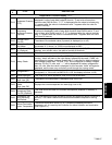
Code Select
Access function codes (see arrow up
and arrow down) for the Controller,
and also for the DataCORDER after
the ALT. MODE key is depressed.
Defrost
Interval
Displays selected defrost interval.
Pre–Trip
Displays a pre-trip selection menu.
Discontinues pre-trip in progress.
Battery
Power
If the unit is equipped with the optional
battery pack, initiate the battery
backup mode to allow set point and
function code selection if no mains
power is present.
Enter
Entering a set point change.
Extending to 30 seconds the time a
chosen data function code is
displayed. Entering the value of auser
selectable mode. Clearing the alarm
list and initiating pre-trip. Also used for
various DataCORDER functions after
the ALT. MODE key is depressed.
ALT. Mode
Allows access to DataCORDER
function codes, alarm codes,
DataCORDER configuration and
scrollback.