


SECTION 6
6-29 T-268-07
NOTE
This p ackaging has been designed to p rotect the
Controller/DataCORDER module from both
physical and electrostatic discharge damage
during storage and transit.
Installation:
Install the module by reversing the steps in section
6.27.b.
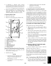
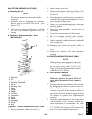
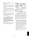
Torque values for mounting screws (item 1,
Figure 6-31) are 0.23 mkg (20 inch-pounds), and 0.12
mkg (10 inch-pounds) for all connectors (MA, MB,
MC, KA & KB).
6.27.1 C ontroller/DataCORDER Programming
Procedure
To load new software into the module, the
programming card is inserted into the
programming/software port.
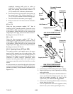
WARNING
The unit must be OFF whenever a
programming card is inserted or removed
from the programming/software port.
The metal door on the programming card
must be facing to the left when inserting.
Procedure for loading Operational Software:
a. Turn unit OFF, via start-stop switch (ST).
b. Insert the programming card for Operational
Software into the programming/software port. (See
Figure 6-31)
c. Turn unit ON, via start-stop switch (ST).
d. The Display module will read:
(1.) If the correct card is being used the digital
display will alternate back and forth between
the messages “rEV XXXX” and “Press EntR.”
(2.) If a defective card is being used: the Display
will blink the message “bAd CArd.” (Turn
start-stop switch OFF and remove the card.)
e. Press the ENTER key on the keypad.
f. The Display will show the message “Pro SoFt.”
This message will last for up to one minute.
g. The Display module will read:
(1.) When the software l oading has successfully
completed: the Display will show the message
“Pro donE.”
(2.) If a problem occurs while loading the software:
the Display will blink the message “Pro FAIL”
or “bad 12V.” (Turn start-stop switch OFF and
remove the card.)
h. Turn unit OFF, via start-stop switch (ST).
i. Remove the programming card from the
programming/software port.
j. Turn unit ON, via start-stop switch (ST).
Procedure for loading Configuration Software:
a. Turn unit OFF using start-stop switch (ST).
b. Insert the programming card, for Configuration
Software, into the programming/software port.
(See F igure 6-31.)
c. Turn unit ON using start-stop switch (ST).
d. The Display module will read:
(1.) If the correct card is being used, the digital
display will show “nt40” on the left LCD
display and “511XXX” on the right LCD
display. “XXX” will indicate the dash number
for a given unit model number, use the UP or
DOWN ARROW key to scroll through the list
to obtain the proper model dash number (i.e.,
For the unit 69NT40-511-105, the left display
will show “nt40,” press the UP or DOWN
ARROW key until the right display shows
“511105.”)
(2.) If a defective card is being used, the Display
will blink the message “bAd CArd.” (Turn
start-stop switch OFF and remove the card.)
e. Press the ENTER key on the keypad.
f. The Display module will read:
(1.) When the software l oading has successfully
completed, the Display will show the message
“EEPrM donE.”
(2.) If a problem occurs while loading the software,
the Display will blink the message “Pro FAIL”
or “bad 12V.” Turn start-stop switch OFF and
remove the card.
g. Turn unit OFF using start-stop switch (ST).
h. Remove the programming card from the
programming/software port.
i. Turn unit ON using start-stop switch (ST).
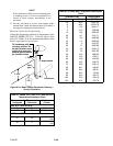
6.27.2 Controller Trouble-Shooting
Agroupof test points(tp)areprovidedon theController
(see Figure 6-31, item 3) for trouble-shooting electrical