


3-6T-268-07
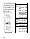
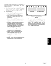
3.1.4 Controller Function Codes
There are thirty-nine functions which the operator may
access to examine the operating status of the unit. To
access these functions, perform the following steps:
Press the CODE SELECT key, then press an arrow key
until the left window displays the desired code number
(seeTable 3-3). For the display only function codes,the
right window will display the value of this item for five
seconds before returning to the normal display mode. If
a longer time is desired, pressing the ENTER key will
extend the time to 30 seconds after the last pressing of
the ENTER key. Function codes are explained in
Table 3-3.
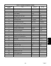
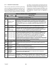
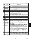
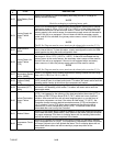
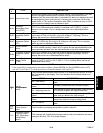
Table 3-3. Controller Function Code Assignments
CODE
#
TITLE DESCRIPTION
Inapplicable Functions Display ----------
Display Only Functions
Cd01
Modulation Valve
Opening (%)
The suction modulation valve (SMV) is a normally open valve which restricts flow
of refrigerant to the compressor when energized by a pulse width modulated
(PWM) output. The amount of valve closure is proportional to the applied current
over the range of 0.2 to 1.3 A. The valve is completely open (right display reads
100%) below 0.2 amps and is completely closed (right display reads 0%) at 1.3
amps.
Cd02
Quench Valve
(Open--Closed)
Shows state of the solenoid quench valve, if so equipped (open or closed).
Cd03
Suction Solenoid
Valve
(Open--Closed)
The suction solenoid valve (SSV) provides maximum refrigerant flow to the
refrigeration unit. This valve will always be open for set points at or below --10_C
(+14_F), or --5_C(+23_F) optionally, and during temperature pulldown periods
unless suction solenoid override or current limiting restricts its use.
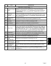
Cd04
Cd05
Cd06
Line Current, Phase
A
Line Current, Phase
B
Line Current, Phase
C
Unit current is monitored by two current sensors. The current measured is used
for control and diagnostic purposes.For control processing, the highest of the
Phase A and B current values is used for current limiting purposes. The third
unmeasured leg is calculated based on a current algorithm. For diagnostic
processing, the current draws are used to determine control unit operations.
Whenever a heater or a motor is turned ON or OFF, the current draw
increase/reduction for that activity is measured. The current draw is then tested to
determine if it falls within the expected range of values for the unit. Failure of this
test will result in a pre-trip failure or a control alarm indication.
Cd07 Main Power Voltage The main supply voltage is displayed.
Cd08
Mains Power
Frequency
The value of the main power frequency is displayed in Hertz. The frequency
displayed will be halved if either fuse F1 or F2 is bad and alarm code AL21 is
active.
Cd09
Ambient
Temperature
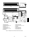
The ambient sensor (AMBS) measures the temperature outside the container.
For location of the sensor, see Figure 2-5.
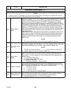
Cd10
Compressor Suction
Temperature
(Optional)
Compressor suction temperature is measured just prior to the compressor suction
service valve, and is a display-only temperature.
Cd11
Compressor
Discharge
Temperature
(Optional)
The compressor discharge temperature is measured near the compressor
discharge valve and is display only.
Cd12
Compressor Suction
Pressure (Optional)
Compressor suction pressure is displayed using a pressure transducer. Pressure
is displayed in units of psig when code 28 is set to _F and units of bars when
code 28 is set to _C. “P” appears after the value to indicate psig, “b” appears after
the value to indicate bars and “i” appears after the value for inches of mercury.