


2-18T-268-07
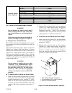
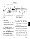
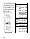
2.10 SUCTION SOLENOID VALVE
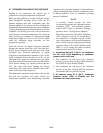
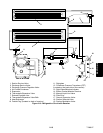
The suction solenoid valve, shown in Figure 2-5, is
controlled by the Controller relay (TS).
a. Operation
If set point is below --10_C(+14_F), or --5_C(+23_F)
optionally, and the suction solenoid valveoverride is not
activated, Controller relay (TS) closes to energize the
suction solenoid valve (SSV). Once opened, the
refrigerant flow rate and u nit cooling capacity i s
increased.
If set point is above --10_C(+14_F), or --5_C(+23_F)
optionally, the suction solenoid valve opens during t he
temperaturepulldownperiod unlessthe currentlimiting
suction solenoid overrides or compressor reliability
enhancement logic restricts its use. A pulldown period
begins when the control temperature is more than 5_C
(+9_F) above set point, and ends as soon as the control
temperature equals set point.
For both conditions above, at the instant when the SSV
opens, the SMV will drop to 20% open, then gradually
increase to 100% open. Unless the current limiting
suction solenoid overrides or compressor reliability
enhancement logic (CREL) restricts its use.
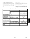
b. Suction Solenoid Override
The suction solenoid override function restricts the
opening of the suction solenoid valve (SS V) under
certain highambient and/or box temperatureconditions
to prevent compressor overload under these high
capacity conditions. If the primary return sensor (RTS)
fails (alarm code AL56), the suction solenoid valve will
not open unless the ambient temperature is less than
10_C(50_F). If the ambient sensor fails (AL57), the
suction solenoid valve will not be allowed to open until
the return air temperature is less than 1.67_C(35_F). If
both the ambient and return air (RTS) sensors fail, the
suction solenoid valve will not be allowed to open until
at least one of the sensors is repaired.
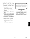
2.11 REMOTE MONITORING (Optional)
NOTE
The in-range light will be illuminated if the
container control air temperature is within the
tolerance selected. Refer to section 3.1.4
(Code 30).
When the remote monitor plug is connected to the
remote monitoring receptacle, the following remote
circuits are energized:
CIRCUIT FUNCTION
Sockets B to A Energizes remote cool light
Sockets C to A Energizes remote defrost light
Sockets D to A Energizes remote in-range light