


4-12T-268-07
4.4.6 Defrost
Refer to section 3.1.4 (Code 27) for description of the
defrost interval selector and automatic defrost
initiation.
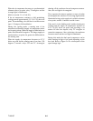
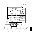
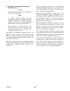
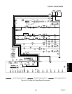
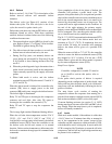
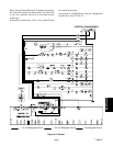
The defrost cycle (see Figure 4-5) consists of two
distinct sub-cycles. The first sub-cycle is the de-ice
cycle, the second is a probe check cycle.
Defrost may take place any timetheDTS allows, andno
shutdown alarms are active. With these conditions
satisfied, defrost is initiated when one of the following
conditions becomes true:
a. The manual defrost switch (MDS) is closed by the
user. Refer to Figure 2-7 or Figure 2-8 for location.
The MDS is ignored during Pre-Trip.
b. The defrost interval timer reaches or exceeds the
defrost interval selected and set by the user.
c. During Pre-Trip (auto, not manual) defrost can
occur during the advanced Pre-Trip tests P-8 and
P-10. Defrost is forced during advanced Pre-Trip
test P-9.
d. When the probe diagnostic logic determines that a
probe check is necessary based on the temperature
values currently reported by the supply and return
probes.
e. When bulb mode is active, and the defrost
terminationsensor(DTS)is between0_C and10_C
(32_F and 50_F).
When the defrost mode is initiated, the controller relay
contacts (TH) close to supply power to the heat
contactor (HR) and in turn, energize the defrost heaters.
The defrost light is illuminated.
Relay TC and TD open to de-energize the compressor
contactor and cool light. Also relay TN opens to
de-energize t he condenser fan contactor (CF).
Relay TE and TV open to stop the evaporator fan
motors.
The in-range light remains illuminated during defrost.
When the coil tube sheet temperature reaches 25.6_C
(78_F), [4_C and 25.6_C (39.2_F and 78_F) if
configured for and operating in bulb mode], the defrost
termination sensor (DTS) causes the controller to end
the defrost cycle and the unit returns to its normal
function. Under certain circumstances,defrost may also
be forced to terminate t hrough special communication
commands.
Upon completion of the de-ice phase of defrost, the
controller will perform a probe check cycle. The
purposeofthe probe checkcycleis toperform aperiodic
check ofthe controller sensors todetect malfunctions or
drift in the sensed temperature that is too small to be
detected by the normal sensor out of range tests. The
system will run for eight minutes in this condition. At
the end of the eight minutes, the primary supply,
primary return and DataCORDER sensor temperatures
will be compared. The controller probe alarms will be
set or cleared based on the conditions seen.
The54.5_C(130_F) heatterminationt hermostat(HTT)
will open the circuit if the defrost mode does not
terminate at 25.6_C(78_F). If termination does not
occur within 2.0 hours, the controller will terminate
defrost. An alarm will be given of a possible DTS
failure.
When the return air falls to 7_C(45_F), the controller
checks to ensure the defrost termination sensor (DTS)
has dropped to 10_C or below. If it has not, a DTS
failure alarm is given and t he defrost mode is operated
by the return temperature sensor (RTS).
Snap Freeze Option:
NOTE
Controller configuration variable 33 must be
set to SnAP to activate this option, refer to
Table 3-1.
If the probe check p ortion of d efrost is required
(depending on the configuration of probe check), snap
freeze will run after the probe check cycle. Otherwise,
snap freeze will run immediately following the de-ice
portion of defrost.
The snap freeze cycle consists of running the
compressor without the evaporator fans running for a
periodoffourminutes withbothsuctionsolenoid(SSV)
and suction modulation (SMV) valves fully open.
If current limiting activates (see section 3.1.4, Cd32)
during snapfreeze, the state o fthe SSV an d SMVvalves
may change. When the snap freeze cycle is completed,
defrost is formally terminated.
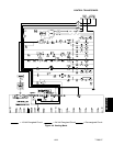
4.4.7 Arctic
With arctic mode enabled, if the ambient is colder than
--10.0_C there is a 30 minute time delay at startup for
any of the components in the system, except for the
controller and the compressor crankcase heater (CCH),
which should be active at this point. In arctic mode, the
CCH is energized for 30 minutes to warm the oil in the
compressor, and boil off any liquid refrigerant that may
be present in the crankcase.