


SECTION 6
6-11 T-268-07
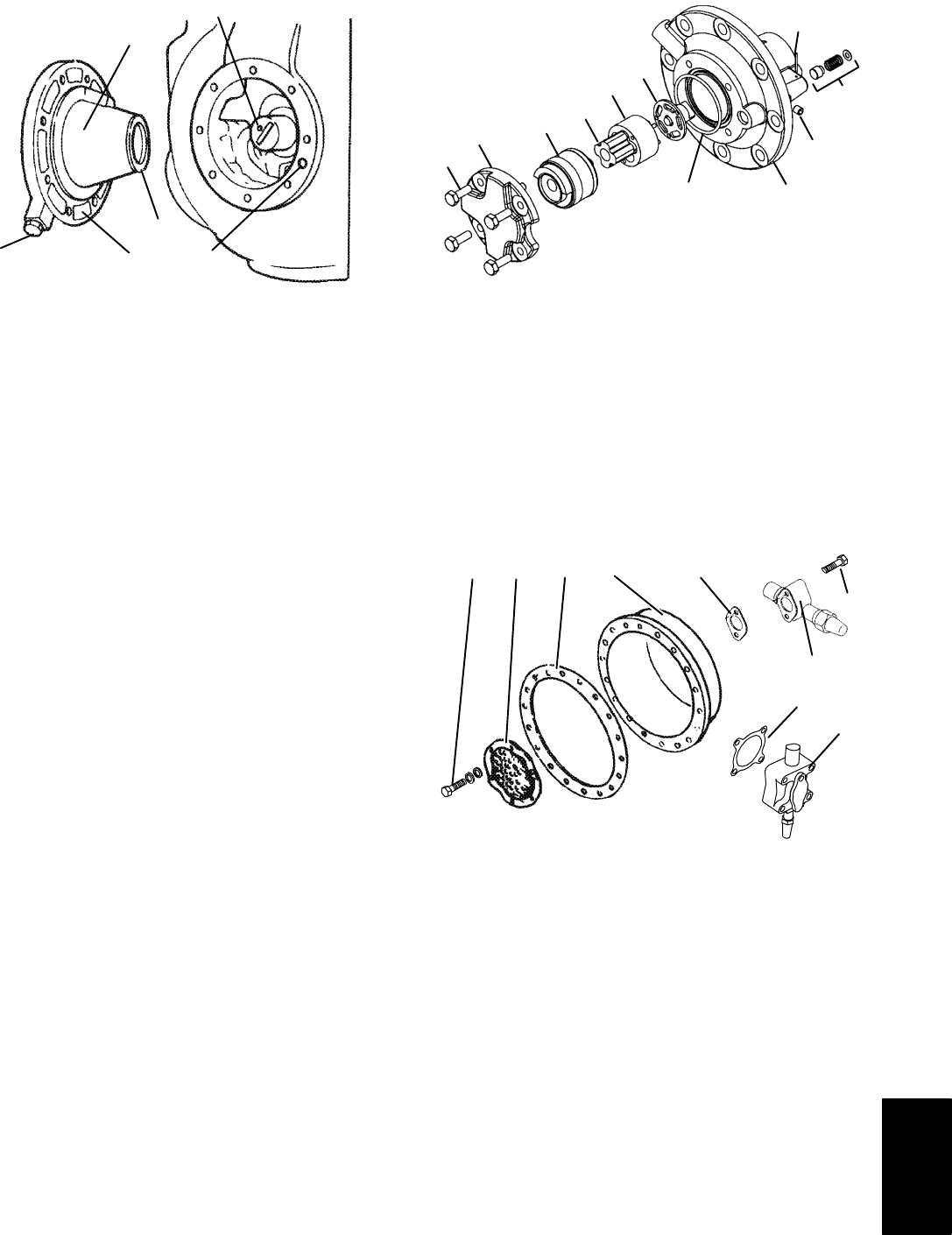
2
1
3
4
5
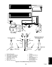
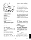
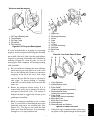
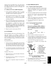
Set screw must be removed.
1. Oil Pump & Bearing Head
2. Thrust Washer
3. Oil Pickup Tube
4. Oil Inlet Port
5. Oil Pump Inlet
Figure 6-8. Oil Pump and Bearing Head
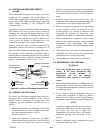
If it was determined that the oil pump is not operating
properly, theentireoil pumpandbearing headassembly
must be replaced. Replacement parts for the pump are
not available. However, in the event the pump requires
inspection or cleaning, disassemble and reassemble by
referring to Figure 6-9. Clean all parts and coat all
moving parts with compressor oil before proceeding
with reassembly.
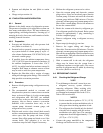
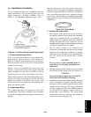
g. Be very careful not to damage the motor windings
when removing the motor end cover, as the cover
fits over the winding coils. Remove all capscrews
except one in the top of the cover. Then, while
holding the cover in place, remove the remaining
capscrew. Do not allow the cover to drop from its
own weight. To prevent striking the winding,
remove the cover horizontally and in line with the
motor axis.
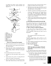
h. Remove the refrigerant suction strainer. If it is
removed with ease it may be cleaned with solvent
and replaced. (See Figure 6-10.) If the strainer is
broken, corroded or clogged with dirt that is not
easily removed, replace the strainer. Install new
gaskets upon reassembly.
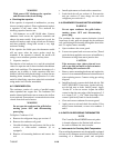
i. Block the compressor crankshaft so that it cannot
turn. Use a screwdriver to bend back the tabs on the
lockwasher and remove the equalizer tube. (See
Figure 6-12.) The slinger at the end of the shaft
draws vapor from the crankcase. It may discharge
through a tee or a single equalizer tube.
1
2
3
4
5
6
7
8
9
10
11
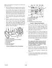
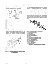
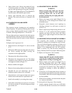
1. Capscrews
2. Cover
3. Reversing Assembly
4. Pinion
5. Gear
6. Drive
7. O-Ring
8. Oil Pump & Bearing
9. Set Screw
10. Relief Valve
11. Pin
Figure 6-9. Low Profile Gear Oil Pump
1
2
36789
4
5
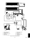
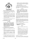
1. Valve Capscrew
2. Suction Service Valve
(Used on single-speed compressor)
3. Valve Gasket
(Used on single-speed compressor)
4. Suction Service Valve
(Used on two-speed compressor)
5. Valve Gasket
(Used on two-speed compressor)
6. Motor End Cover
7. Motor End Cover Gasket
8. Suction Strainer
9. Strainer Screws and Washers
Figure 6-10. Motor End Cover
j. If the piston rings extend beyond the cylinder tops,
the pistons can be pulled through the bottom plate