


SECTION 6
6-15 T-268-07
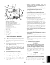
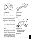
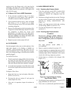
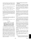
suction service valve flange cavity or by removing the
oil fill plug. (See Figure 6-5.) Some compressors have
the oil plug located on the crankcase, at the right or left
side of the oil pump.
d. To Remove Oil From an 06DR Compressor:
1. If the oil level recorded in step a.3 is above
one-eighth level of the capacity of the sight glass,
oil must be removed from the compressor.
2. Close (frontseat) suction service valve and pump
unit down to 1.2 to 1.3 kg/cm@ (2 to 4 psig).
Frontseat discharge service valve and slowly bleed
remaining refrigerant.
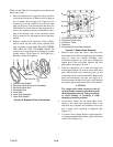
3. Removetheoil drainplug onthe bottomplate ofthe
compressor and drain the proper amount of oil from
the compressor to obtain the correct level
(maximum is one-eight level of the sight glass).
Replacetheplugsecurely backinto thecompressor.
DO NOT FORGET TO OPEN SUCTION AND
DISCHARGE SERVICE VALVES.
4. Repeat step (a) t o ensure proper oil level.
6.11 FILTER-DRIER
On unitsequipped with awater-cooled condenser, if the
sight glass appears to be flashing or bubbles are
constantly moving through the s ight glass when the
suction modulation valve is fully open, the unit may
have a low refrigerant charge or the filter-drier could be
partially plugged.
To Check Filter-Drier:
a. Testforarestrictedor pluggedfilter-drierbyfeeling
the liquid line inlet and outlet connections of the
driercartridge.If the outlet side feelscooler than the
inlet side, then the filter-drier should be changed.
b. A second test for moisture in the filter-drier is that
the moisture-liquid indicator shows moisture in the
system.
To Replace Filter-Drier:
a. Pump unit down to 0 psi and replace filter-drier.
(Refer to section 6.3.)
b. Evacuate the unit per section 6.5 and open the
manual liquid line valve.
c. After unit is i n operation, inspect for moisture in
system.
6.12 HIGH PRESSURE SWITCH
6.12.1 R eplacing High Pressure Switch
a. Turn unit start-stop switch OFF. Frontseat both
suction and discharge service valves to isolate
compressor. Remove the refrigerant from the
compressor.
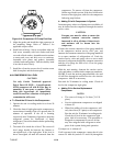
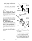
b. Disconnect wiring from defective switch. The high
pressure switch is located on the center head and is
removed by turning counterclockwise. (See
Figure 2-1.)
c. Install a new high pressure switch after verifying
switch settings. (Refer to section 6. 12.2.)
d. Evacuate and dehydrate the compressor per
section 6.5.1.
6.12.2 C hecking High Pressure Switch
WARNING
Do not use a nitrogen cylinder without a
pressure regulator. Do not use oxygen in or
near a refrigeration system as an explosion
may occur.
NOTE
The high pressure switch (HPS) is
non-adjustable.
a. Remove switch as outlined in section 6.12.1.
b. Connect ohmmeterorcontinuity lightacrossswitch
terminals. Ohm meter will indicate no resistance or
continuity light will be illuminated if the switch
closed after relieving compressor pressure.
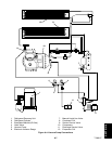
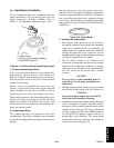
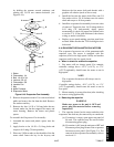
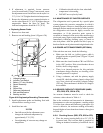
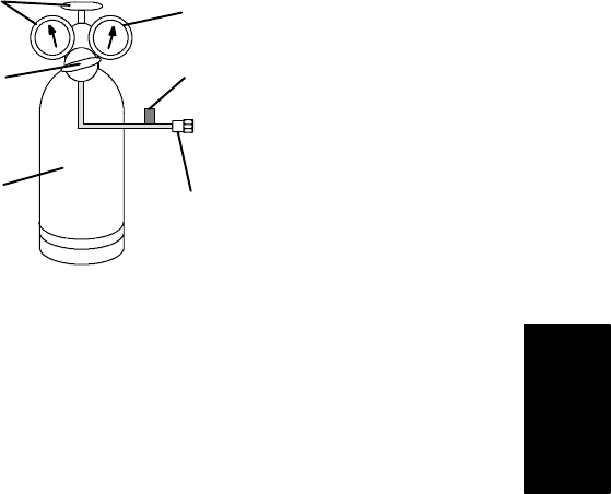
c. Connect hose to a cylinder of dry nitrogen. (See
Figure 6-17.)
1. Cylinder Valve
and Gauge
2. Pressure Regulator
3. Nitrogen Cylinder
4. Pressure Gauge
(0 to 36 kg/cm@ =
0 to 400 psig)
5. Bleed-Off Valve
6. 1/4 inch Connection
1
2
3
4
5
6
Figure 6-17. Typical Setup for Testing
High Pressure Switch
d. Set nitrogen pressure regulator at 26.4 kg/cm@ (375
psig) with bleed-off valve closed.
e. Close valve on cylinder and open bleed-off valve.