


SECTION 6
6-27 T-268-07
6
2
5
3
7
1
4
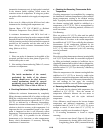
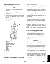
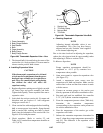
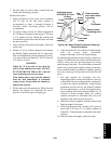
1. Power Assembly
2. Body Flange Gaskets
3. Seat Gasket
4. Bulb
5. Cage Assembly
6. Body Flange
7. Body Flange Screws
Figure 6- 29. Therm ost atic Expa nsion V alv e -- Alc o
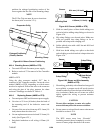
5. The thermal bulb i s located below the center of the
suction line (4 o’clock position). This area must be
clean to ensure positive bulb contact.
b. Installing Expansion Valve
CAUTION
If the thermostatic expansion valve is found
to be in need of replacement, then the power
head and cage assembly are to replaced as a
pair. They are a matched pair and replacing
one without the other will affect the
superheat setting.
1. Replace allgaskets, makingsure t olightly coatwith
oil. Insert cage and power assembly and bolts.
Tighten bolts equally. Fasten equalizer flare nut to
expansion valve.
2. Leak check the unit per section 6.4. Evacuate and
dehydrate unit per section 6.5. Add refrigerant
charge per section 6.6.2.
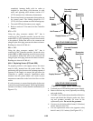
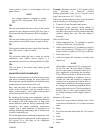
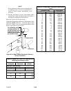
3. Clean suction line with sandpaper before installing
bulb to ensure proper heat transfer. Strap thermal
bulb to suction line, making sure bulb is placed
firmly into the indentation of the suction line. See
Figure 6-30 for bulb placement.
4. Check superheat. (Refer to section 2.2 and
Table 6-6.) Container box temperature should be at
-- 1 8 _C(0_F).
1
2
3
4
1. Suction Line
2. TXV Bulb Clamp
3. Nut and Bolt
4. TXV Bulb
Figure 6- 30. The rm osta tic Expans ion Va lve Bulb
c. Checking Superheat
NOTE
Adjusting internal adjustable valves is not
recommended. This valve has been factory
adjusted and set with “Locktite” that is applied
to the internal adjusting nut.
Due to the time involved in adjusting the superheat,
replace the valve (power head & cage assembly) rather
than adjusting it. Refer to section 6. 26.b.
To Measure Superheat:
NOTE
Proper superheat measurement should be
completed at --18_C(0_F) container box
temperature where possible.
1. Open access panel to expose the expansion valve
(see Figure 2-1).
2. Attach a temperature tester sensor near the
expansion valve bulb and insulate. Make sure the
suction line is clean and that firm contact is made
with the sensor.
3. Connect an accurate gauge to the service port
directly upstream of the suction modulation valve.
4. Run unit until unit has stabilized. Set controller
5.5_C(10_F) below container temperature.
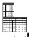
5. From the temperature/pressure chart (Table 6-6),
determine the saturation temperature
corresponding to the evaporator outlet pressure at
the suction modulation valve.
6. Note the temperature of the suction gas at the
expansion valve bulb.
7. Subtract the saturation temperature determined in
step (5.) from the average temperature measured in
step (6.). The difference is the superheat of the
suction gas.