


3-24T-268-07
CODE
#
DESCRIPTIONTITLE
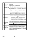
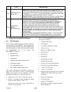
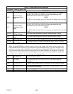
P10-1
Frozen Mode (Pull
Down) Test
Setup: When the container temperature is greater than or equal to the 45_F. set
point which was set in the frozen mode heat test, the left display will read “P101”
and the right display will show the return air temperature. The set point will then
be changed to --17.7_C(0_F). The unit will then have a maximum of three hours
to pull the container temperature down to the 0_F set point.
Pass/Fail Criteria: If this occurs within the three hour time limit, the test passes.
If pulldown is not completed within the three hour time limit, the test fails.
P10-2
Frozen Mode
Maintain
Temperature Test
Setup: After the unit has successfully completed the frozen pulldown test, the
left display will read “P102” and the right display will show the return air
temperature. The unit will then be required to maintain the 0_F temperature
within + or -- 0.5_C(0.9_F) of set point until a DataCORDER recording is
executed. The recorder return probe temperature running total (and its
associated readings counter) will be zeroed out for the remainder of the
recording period at the start of this test, so that the actual value recorded in the
DataCORDER will be an average of only this test’s results. Once the recording
interval is complete, the average recorder return temperature will be recorded in
the DataCORDER, as well as stored in memory for use in applying the test
pass/fail criteria.
Pass/Fail Criteria: If the recorded temperature is within +/-- 0.5_C of set point
from test start to DataCORDER recording, the test passes. If temperature is
outside of the tolerance range at the DataCORDER recording, the test fails.
3.3 INTEGRATED DATACORDER (OPTIONAL)
3.3.1 Brief Description
Carrier Transicold has developed a recorder, which we
havetermed the“DataCORDER,” andis integratedinto
a module with the Controller. For reader simplicity and
understanding thissectionhas beenseparated toexplain
the DataCORDER side of the module. The
DataCORDER consists of:
S Micr oprocessor
S Progr am memor y
S Da ta me mory
S Inte rnally batter y back ed re al time clock
S Six ther mistor inputs
S Two c ommunication por ts
S Power supply (optional ba ttery pa ck).
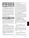
This recorder eliminates the mechanical recorder and
paper chart, and replaces it with a custom-designed
module (see Figure 3-1) that interfaces with the
Interrogator and operates in the following ways:
a. Logs data at 15, 30, 60 or 120 minute intervals.
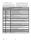
b. Records and displays alarms through the digital
display module. (Refer to Table 3-7.)
c. Stores at least two years’ worth of data based on
typical one hour intervals.
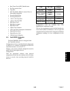
d. Records DataCORDER/Network generated data
and events as follows:
S Container ID Change
S S/W Upgrade
S Controller configuration change
S Alarm Activity
S Battery Low (Battery Pack)
S Data Retrieval
S Defrost Start
S Defrost End
S Dehumidification S tart
S Dehumidification End
S Power Loss (w/wo battery backup)
S Power Up (w/wo battery backup)
S “Auto 1” Pre-Trip Start
S “Auto 1” Pre-Trip End
S Remote Probe Temperatures in the Container
(USDA Cold treatment and Cargo probe
recording)
S Return Air Temperature
S Set Point Change
S Supply Air Temperature
S Real Time Clock (RTC) Battery (Internal
Battery) Replaced