


SECTION 2
2-1 T-268-07
SECTION 2
DESCRIPTION
2.1 GENERAL DESCRIPTION
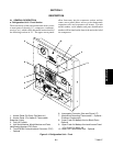
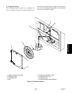
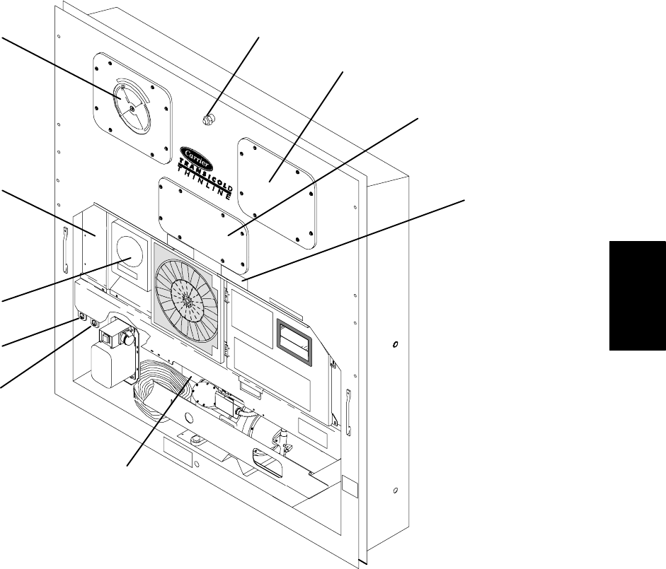
a. Refrigeration Unit -- Front Section
The front section of the refrigeration unit shows access
to most parts of the unit (i.e., compressor, condenser,
receiver, etc.), which will be discussed in more detail of
the following sections in 2.1. The upper access panels
allow front entry into the evaporator section, and the
center access panel allows access to the thermostatic
expansion valve and evaporator coil heaters. The unit
model number, serial number and parts identification
numberwillbe found onthefrontofthe unittotheleftof
the compressor.
1
2
3
4
5
6
7
8
9
10
1. Access Panel (For Evap. Fan Motor #1)
2. Access Panel (For Heater & Thermostatic
Expansion Valve)
3. Fork Lift Pockets
4. Unit Serial Number, Model Number and Parts
Identification Number (PID) Plate
5. TransFRESH Communications Connector (TCC)
-- Optional
6. Interrogator Connector (Also see Figure 2-7)
7. Mechanical Recording Thermometer -- Optional --
(Partlow or Saginomiya)
8. Lower Fresh Air Makeup Vent or Blank Plate --
Optional
9. Upper Fresh Air Makeup Vent and Access Panel
(For Evap. Fan Motor #2)
10. Return Air Thermometer Port -- Optional
Figure 2-1. Refrigeration Unit -- Front